
Rotor head structure of gyroplane and control method of gyroplane vertical launching

A rotorcraft and rotor head technology, applied in the field of rotorcraft, can solve the problems that the rotorcraft cannot take off vertically, reduce the glide distance of the rotorcraft, and the ability to resist wind flow needs to be improved, so as to improve flight stability and safety, and automate The effect of high degree and improved wind resistance

Inactive Publication Date: 2012-10-03
CHONGQING YUYI MACHINE
View PDF0 Cites 1 Cited by
  • Summary
  • Abstract
  • Description
  • Claims
  • Application Information

AI Technical Summary

Problems solved by technology

In order to reduce the run-up distance for take-off, there is also an improved rotorcraft in the prior art. On the basis of the above-mentioned rotorcraft structure, a drive system connected with the rotor is added. The transmission mechanism of the drive system is provided with a clutch. When the clutch is closed, the drive system directly provides power to the rotor, controls the rotation of the rotor to generate lift, and then disengages the clutch, which can greatly reduce the gliding distance of the rotorcraft, but still cannot achieve the vertical takeoff of the rotorcraft
In addition, the existing rotorcraft still needs to be improved in the wind current resistance when encountering the wind current during flight.

Method used


Image

  • Rotor head structure of gyroplane and control method of gyroplane vertical launching
  • Rotor head structure of gyroplane and control method of gyroplane vertical launching

Examples


Embodiment Construction

[0020] The structure of the present invention will be further described in detail below in conjunction with the accompanying drawings and specific embodiments.

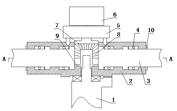
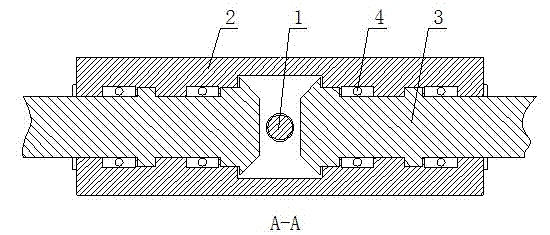
[0021] In specific implementation, such as Figure 1 to Figure 2 As shown, the rotorcraft rotor head structure of the present invention includes a vertically arranged support rod 1, a support base 2 rotatably arranged on the support rod 1, and a rotor connecting rod 3 transversely connected in the support base 2, wherein the The rotor connecting rod 3 is rotatably connected to the support base 2 by the bearing 4, and the support base 2 is provided with a transmission 5 and a connected stepping motor 6, and the output shaft of the transmission 5 extends vertically into the support base 2 And a bevel gear 7 is arranged at the end, and one end of the rotor connecting rod 3 located in the support seat 2 is provided with a bevel gear 8 to mesh with the bevel gear 7 . During implementation, the upper part of one end of the...


PUM


Abstract

The invention discloses a rotor head structure of a gyroplane. The structure comprises a support rod, a support seat and a rotor wing connecting rod, wherein the support rod is arranged vertically; the support seat is rotationally arranged on the support rod; and the rotor wing connecting rod is transversely connected to the inside of the support seat. The structure is characterized in that: the rotor wing connecting rod is rotationally connected to the support seat through a bearing; the support seat is provided with a transmission and a stepper motor connected with the transmission; an output shaft of the transmission vertically extends into the support seat, and the end head of the output shaft is provided with a bevel gear; and one end, which is positioned in the support seat, of the rotor wing connecting rod is provided with a conical gear engaged with the bevel gear. The invention also discloses a rotor head structure-based gyroplane and a method for controlling vertical take-off of the gyroplane. The structure can realize the vertical take-off of the gyroplane and enhances the flight stability and safety of the gyroplane.

Description

technical field [0001] The invention relates to the field of rotorcraft in aircraft, in particular to the rotor head structure of the rotorcraft. Background technique [0002] A gyroplane is a rotorcraft that utilizes the relative airflow during forward flight to blow the rotor to rotate to generate lift. Its forward force is directly provided by the engine driving the propeller. Ordinary gyroplanes must roll and accelerate to take off. [0003] At first glance, gyroplanes and helicopters are exactly the same: they all have a pair of large-diameter rotors on their heads, and rely on the rotation of the rotors to generate lift during flight. But despite these apparent similarities, gyroplanes and helicopters are two entirely different aircraft. Gyrogyro is actually a kind of aircraft between helicopter and airplane, and it removes outside rotor, also has a pair of propeller usually to provide the power that advances, and generally less wing also is housed and provides part...

Claims


Application Information

Patent Timeline
Patent Type & Authority Patents(China)
IPC IPC(8): B64C27/32B64C27/02G05D1/08
Inventor 冉泽环张勇
Owner CHONGQING YUYI MACHINE
Learn More