

Knitting needle for tricot machine
A technology of warp knitting machines and knitting needles, which is applied in knitting, textiles and papermaking, etc. It can solve the problems affecting the installation and positioning of warp knitting machine needle beds, affecting the stability and reliability of knitting needles, and achieves simple positioning Reliable, stable grip and improved fabric quality
- Summary
- Abstract
- Description
- Claims
- Application Information
AI Technical Summary
Problems solved by technology
Method used
Image

Examples
Embodiment 1
[0015] Embodiment 1, a kind of knitting needle suitable for tricot machine:
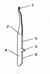
[0016] Refer to attached figure 1 : The designed knitting needle for this warp knitting machine includes needle hook 1, needle bar 2, stitches 3, needle tail 4 and needle bed, and the needle bar is a straight or curved sheet structure, and the needle bar The thickness is consistent, and the front end of the needle bar is provided with a needle hook 1. The needle hook is thin cylindrical, and its diameter is slightly smaller than the thickness of the needle bar. There is a convex stitch 3 in the middle of the needle bar, and the planes 5 and 6 on both sides of the stitch on the same plane.
Embodiment 2
[0017] Embodiment 2, a kind of knitting needle suitable for Raschel warp knitting machine:
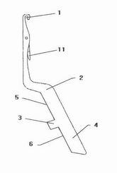
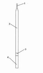
[0018] Refer to attached image 3 , the design of this knitting needle for warp knitting machines includes a needle hook 1, a needle bar 2, a stitch 3 and a needle tail 4. The needle bar is curved and has a sheet structure, the thickness of the needle bar is the same, and the front end of the needle bar A needle hook 1 is provided, and the needle hook is thin cylindrical, and its diameter is slightly smaller than the thickness of the needle shaft; a needle latch 11 is provided at the rear of the needle hook; the length of the needle tail 4 is 1-12 mm, and the width is 2-2 mm. 4mm, the thickness is 0.1-1. 0 mm; there is a convex stitch 3 in the middle of the needle bar, and the planes 5 and 6 on both sides of the stitch are on the same plane.
[0019] When used, (see Figure 4 ) The knitting needles for the warp knitting machine are installed side by side on the needle bed of the war...
PUM
| Property | Measurement | Unit |
|---|---|---|
| Length | aaaaa | aaaaa |
| Width | aaaaa | aaaaa |
| Thickness | aaaaa | aaaaa |
Abstract
Description
Claims
Application Information