Airtight type electric compressor

An electric compressor, airtight technology, used in machines/engines, liquid fuel engines, mechanical equipment, etc., to achieve the effect of less iron loss

Inactive Publication Date: 2011-03-16
HITACHI APPLIANCES INC
View PDF8 Cites 0 Cited by
  • Summary
  • Abstract
  • Description
  • Claims
  • Application Information

AI Technical Summary

Problems solved by technology

The iron loss accounts for a large proportion of the loss generated by the sta

Method used


Image

  • Airtight type electric compressor
  • Airtight type electric compressor
  • Airtight type electric compressor

Examples


Example Embodiment

[0040] Hereinafter, embodiments of the present invention will be described with reference to the drawings.
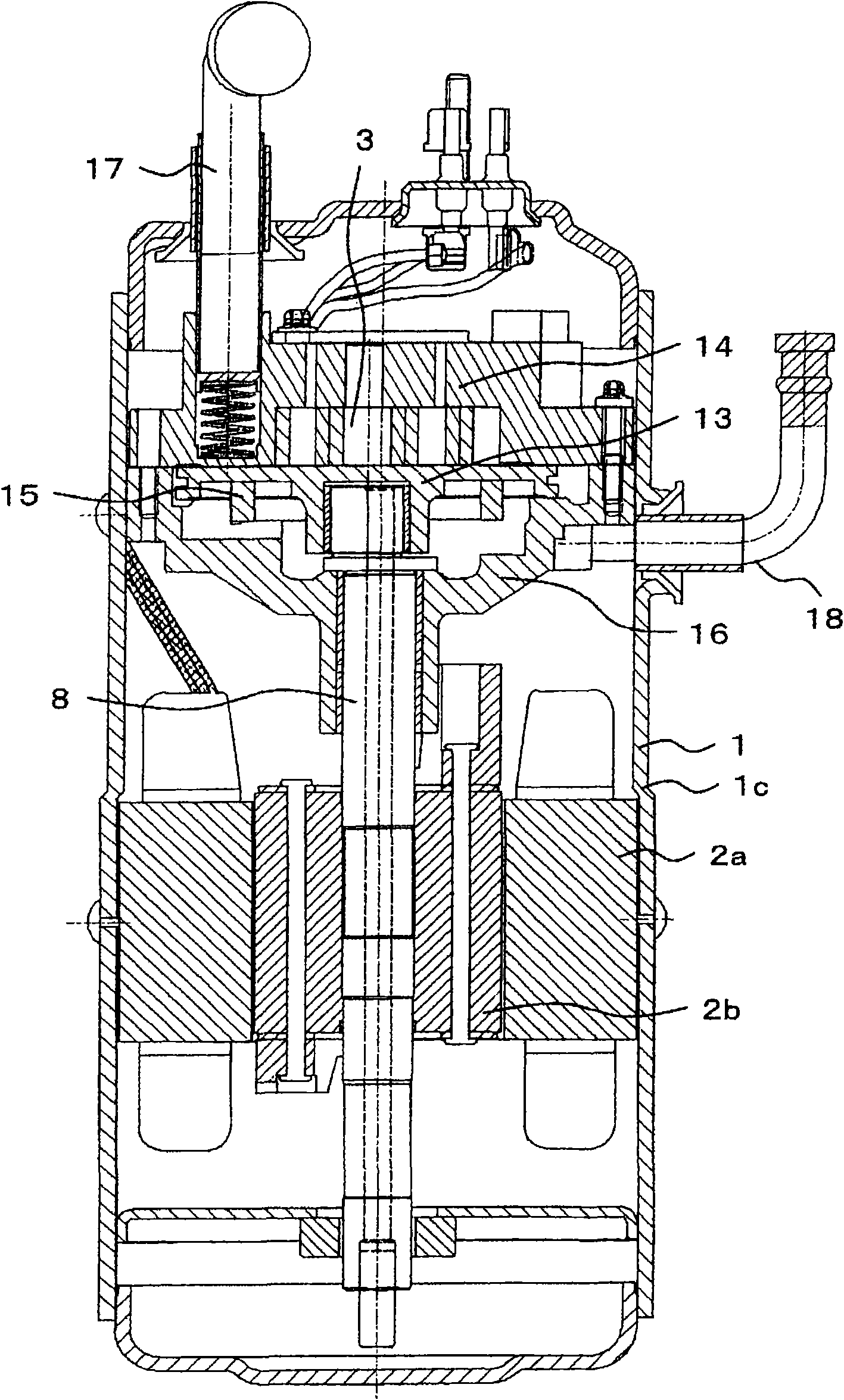
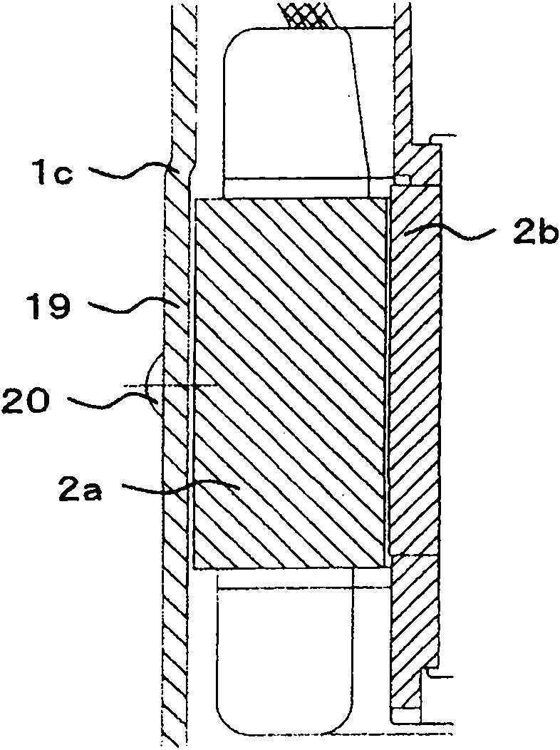
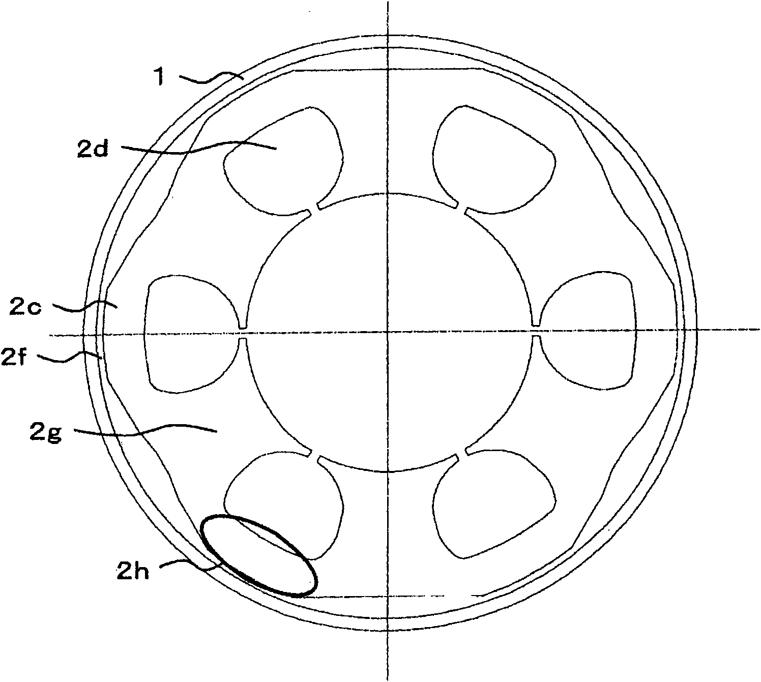
[0041] Regarding the first embodiment, refer to Figure 1 ~ Figure 3 Be explained. figure 1 It is a cross-sectional view of a vertical scroll compressor. As the main structure, a motor 2 which is an electric element and a compression mechanism 3 which is an electric element that compresses the refrigerant between the orbiting scroll 13 and the fixed scroll 14 driven by the motor 2 are arranged inside the airtight container 1. The scroll compression mechanism has an Euclid as a rotation restricting member that supports and guides the fixed scroll 14 and the fixed member 16 so that the orbiting scroll 13 does not rotate relative to the fixed scroll 14 and performs a orbiting motion. Ring 15. The motor 2 includes a stator 2 a and a rotor 2 b. The stator 2 a is fixed to the airtight container 1, and the rotor 2 b is press-fitted and fixed to the shaft 8.

[0042] The compres...


PUM


Abstract

In recent years, in order to save energy, efficiency of electric appliances need to improve. Loss caused by a stator inside a compressor, namely great specific gravity of iron loss, may be improved. The aim of the present invention is to provide a compressor with iron loss. By means of expanding a section of an airtight container corresponding to an axial length of the stator, and welded fastening the stator with the expanding section of the airtight container, iron loss of the compressor can be reduced. Furthermore, a compressor with good efficiency can be implemented.

Description

technical field [0001] The present invention relates to a hermetic electric compressor used in a refrigeration cycle device. Background technique [0002] Patent Document 1 is known as a conventional hermetic electric compressor. Figure 4 It is a vertical cross-sectional view showing a rotary compressor of a hermetic compressor. It is the first figure itself of Patent Document 1, and only the symbols have been changed. exist Figure 4 Among them, 1 is an airtight container, the upper part accommodates the electric element, and the lower part accommodates the compression element. 2a is a stator, and the connection between the stator 2a and the airtight container 1 is affixed to the welded portion 12 via a gap. The technology disclosed in Patent Document 1 is a technology aimed at reducing noise. On the second page, the upper right, second line states that "the connection between the welding part 4 and the stator 2 is approximately point contact through the gap 4a, and beca...

Claims


Application Information

Patent Timeline
IPC IPC(8): F04C18/02
Inventor 村上晃启新村修平岛田敦藤村和幸田所哲也大沼敦
Owner HITACHI APPLIANCES INC
Why Eureka
Try Eureka