Regenerative burner and heat treating furnace

A heat treatment furnace and burner technology, applied in the direction of burners, gas fuel burners, combustion methods, etc., can solve the problems of reduced productivity and low operating efficiency

Active Publication Date: 2011-03-16
CHUGAI RO CO LTD
View PDF11 Cites 3 Cited by
  • Summary
  • Abstract
  • Description
  • Claims
  • Application Information

AI Technical Summary

Problems solved by technology

[0006] However, when removing deposits such as metals adhering to the air supply and exhaust ports in this way, there is a problem that it takes a very long time to stop the combustion of the regenerative burner and sufficiently lower the temperature in the heat treatment furnace. The efficiency is very low. In addition, it takes a long time to burn again to make the temperature in the heat treatment furnace high enough, and the productivity is greatly reduced.

Method used


Image

  • Regenerative burner and heat treating furnace
  • Regenerative burner and heat treating furnace
  • Regenerative burner and heat treating furnace

Examples


Embodiment Construction

[0050] Hereinafter, a regenerative burner and a heat treatment furnace according to an embodiment of the present invention will be specifically described with reference to the drawings. The regenerative burner and heat treatment furnace according to the present invention are not limited to the following embodiments, and can be implemented with appropriate changes within a range that does not change the gist of the invention.

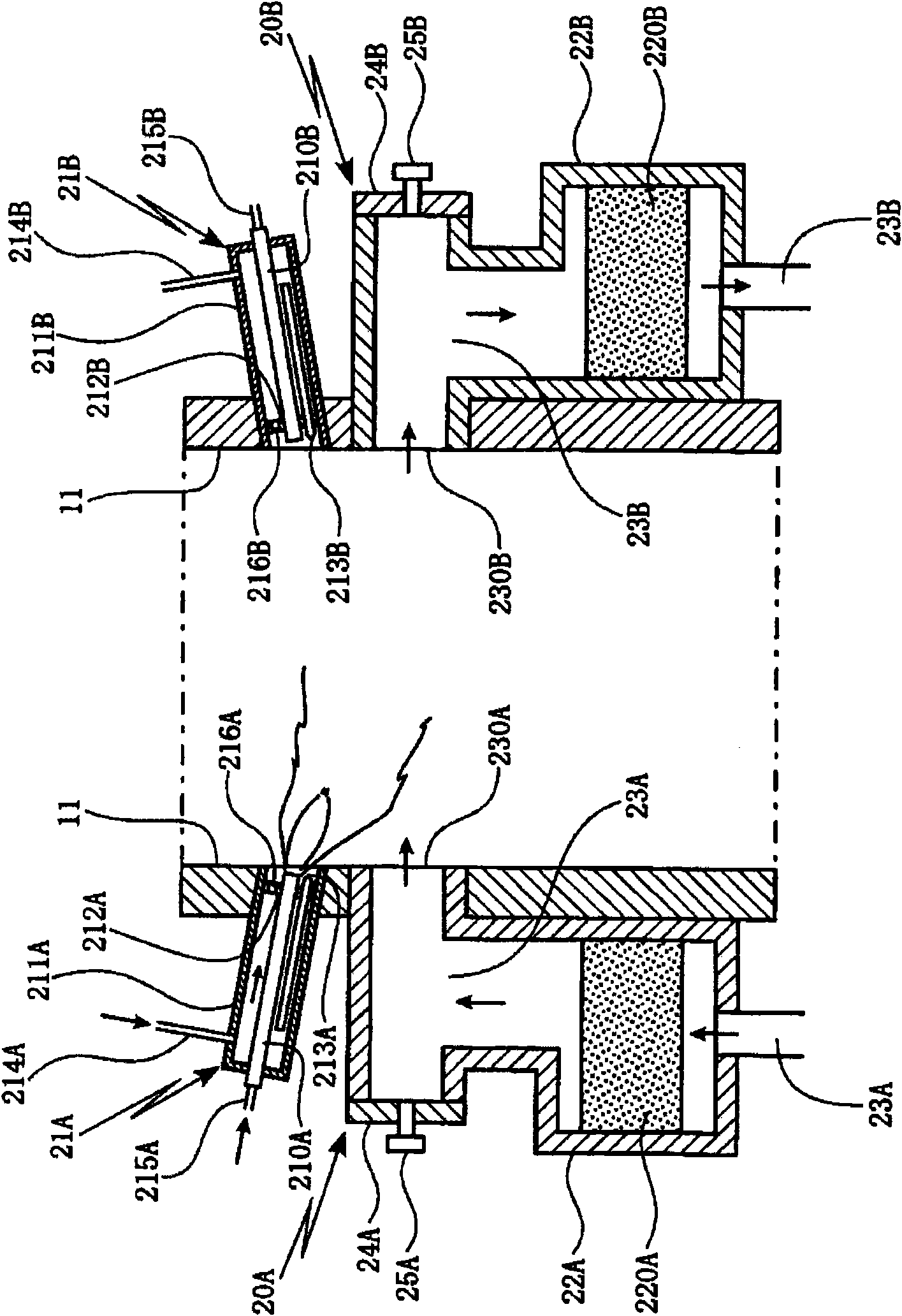
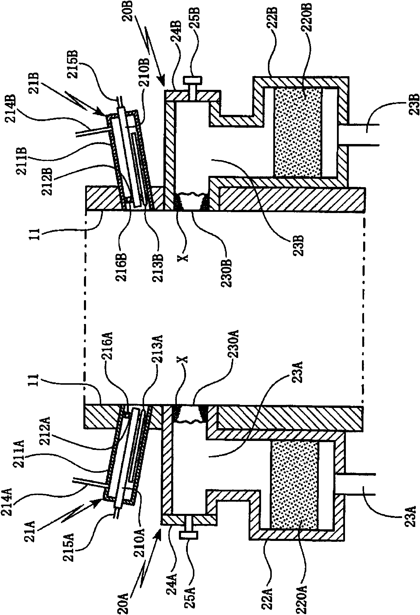
[0051] Such as figure 1 As shown, in this embodiment, a pair of regenerative burners 20A and 20B are provided facing each other on the opposing wall surfaces 11 of the heat treatment furnace 10 .

[0052]Combustion parts 21A, 21B, regenerators 22A, 22B, and supply and exhaust passages 23A, 23B are provided in each of the above-mentioned regenerative burners 20A, 20B, wherein the combustion parts 21A, 21B let fuel flow from each fuel injection nozzle 210A , 210B are ejected and burned, regenerators 22A, 22B contain regenerators 220A, 220B, supply and exh...


PUM


Abstract

A heat treating furnace employing a regenerative burner, wherein the regenerative burner includes: a burning part configured to eject fuel from a fuel ejecting nozzle to burn; a regenerative chamber configured to accept regenerative material; and an exhaust path configured to discharge from the regenerative chamber to the heat treating furnace through an exhaust outlet, in the heat treating furnace, attachment attached to the exhaust outlet can be removed simply. In the regenerative burner (20) having the burning part (21), the regenerative chamber (22) and the exhaust path (23), a door (24) for maintenance is arranged on the exhaust path between the exhaust outlet and the regenerative chamber, the door for maintenance is opened and the attachment (X) attached to the exhaust outlet is cleaned by a cleaning component (30), wherein the burning part (21) is configured to make the fuel to be ejected from the fuel ejecting nozzle (210) to burn, the regenerative chamber (22) accepts regenerative material (220), and the exhaust path (23) discharges from the regenerative chamber to the heat treating furnace (10) through the exhaust outlet (230).

Description

technical field [0001] The present invention relates to a regenerative burner and a heat treatment furnace using the regenerative burner, wherein the regenerative burner includes: a combustion part that injects fuel from a fuel injection nozzle and burns it; The regenerator of the material; the air supply and exhaust passage that makes the combustion air be supplied to the heat treatment furnace from the supply and exhaust port through the regenerator, and the combustion exhaust gas in the heat treatment furnace is discharged from the supply and exhaust port through the regenerator. In particular, it is characterized in that when a metal such as aluminum is melted in a heat treatment furnace using a regenerative burner and a material to be treated is heat-treated, when metals such as aluminum and various impurities generated from the material to be processed are deposited When adhering to the supply and exhaust ports of the above-mentioned regenerative burner, such adhering su...

Claims


Application Information

Patent Timeline
IPC IPC(8): F23D14/00
CPCY02E20/34F23D14/22F23D14/58F23D14/66F23D14/72F23D2900/00002F23L15/02F27D99/0033
Inventor 北村和也河本祐作
Owner CHUGAI RO CO LTD
Why Eureka
Try Eureka