
Differential pressure type liquid level measurement device for pressure container

A liquid level measurement device and pressure vessel technology, which is applied in the direction of displaying liquid level indicators through pressure measurement, can solve the problems of high manufacturing cost, affecting the pressure of positive pressure pipes, and water level measurement errors, so as to achieve low manufacturing cost and avoid measurement effect of error

Inactive Publication Date: 2011-03-16
SHENYANG INST OF ENG +1
View PDF3 Cites 15 Cited by
  • Summary
  • Abstract
  • Description
  • Claims
  • Application Information

AI Technical Summary

Problems solved by technology

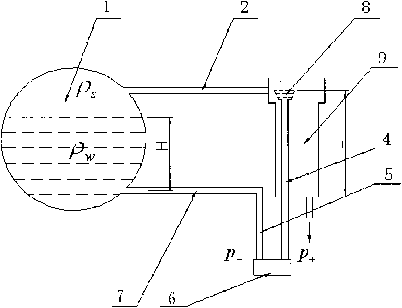
[0011] However, the double-chamber balance container method also has many shortcomings: ①When the boiler is started, the reference water column cannot be condensed into the balance container of the differential pressure water level gauge, and water needs to be manually injected into the inner and outer chambers of the balance container, and the water injection method is complicated.
②Vapor bubbles often appear in the positive pressure tube, and even the upper water level of the inner chamber cannot be filled. Error in water level measurement
③In order to ensure that the water in the inner chamber and the positive pressure pipe connected to it remains in a saturated state, the outer chamber must have enough space for steam to heat the inner chamber, and the larger the size of the outer chamber, the higher its manufacturing cost
④ The position of the differential pressure transmitter is installed below the zero point of the level of the steam drum. The advantage is that the installation position has a large degree of freedom and is convenient, but the problems are also very prominent: The properties such as the density of water must be the same, otherwise it will cause measurement errors
In actual engineering, since the operating conditions and the insulation conditions of the two pipes cannot be completely consistent, measurement errors cannot be avoided

Method used


Image

  • Differential pressure type liquid level measurement device for pressure container
  • Differential pressure type liquid level measurement device for pressure container
  • Differential pressure type liquid level measurement device for pressure container

Examples


Embodiment Construction

[0022] The specific structure, principle and working process of the present invention will be further described below in conjunction with the accompanying drawings.

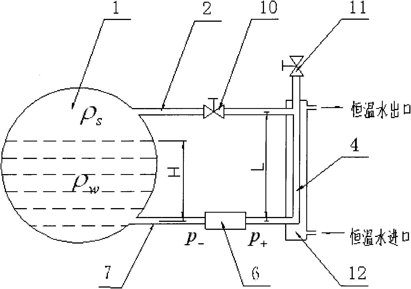
[0023] image 3 A schematic diagram of the principle of the differential pressure liquid level measuring device provided by the present invention, the device includes a steam outlet pipe 2, a saturated water outlet pipe 7, a positive pressure pipe 4 and a differential pressure transmitter 6, and is characterized in that: the steam outlet pipe The pipe is directly connected to the positive pressure pipe 4, and an isolation valve 10 is installed on the steam outlet pipe; the positive pressure pipe is arranged in a thermostatic outer casing 12 filled with a constant temperature fluid, and a water injection valve 11 is installed on the top of the positive pressure pipe; The saturated water outlet pipe and the negative pressure pipe are combined into one, installed at the zero point of the horizontal elevation of the ...


PUM


Abstract

The invention discloses a differential pressure type liquid level measurement device for a pressure container, and relates to liquid level measurement technology of the pressure container. The device comprises a steam lead-out pipe, a saturated water lead-out pipe, a positive pressure pipe and a differential pressure transmitter, wherein the steam lead-out pipe is directly connected with the positive pressure pipe and an isolating valve is arranged on the steam lead-out pipe; the positive pressure pipe is arranged in an outer constant-temperature sleeve in which constant-temperature fluid is held; the top end of the positive pressure pipe is provided with a water injection valve; the saturated water lead-out pipe and a negative pressure pipe are combined into a whole and horizontally arranged at a zero position at the horizontal level of a high-pressure container; and the differential pressure transmitter is arranged on the saturated water lead-out pipe which is connected with the positive pressure pipe through the differential pressure transmitter. The device effectively overcomes the disadvantages of indefinite density and liquid level caused by bubbling, vaporizing and the like of water in the positive pressure pipe and measurement error caused by the mounting position of the differential pressure transmitter in a single-chamber balance container method and a double-chamber balance container method, and has obvious characteristics of high measurement accuracy, convenience of use and low manufacturing cost.

Description

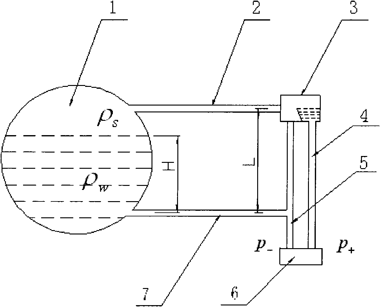
technical field [0001] The invention relates to a differential pressure liquid level measurement device, in particular to a differential pressure liquid level measurement technology for pressure vessels such as steam drums. Background technique [0002] At present, there are two most commonly used methods for water level measurement of pressure vessels such as steam drums, one is the single-chamber balance vessel method, and the other is the double-chamber balance vessel method. [0003] figure 1 It is a schematic diagram of the principle of the single-chamber balance vessel steam drum water level measurement method. The upper part of the steam drum 1 is the steam space, filled with a density of ρ s Saturated steam; the lower part is the density ρ w In the space saturated with water, the drum water level is H. There is a steam outlet pipe 2 connected to the balance container 3 in the steam space on the upper part of the steam drum. There are two pressure measuring tubes...

Claims


Application Information

Patent Timeline
IPC IPC(8): G01F23/16
Inventor 刘吉堂吕俊复
Owner SHENYANG INST OF ENG
Learn More