Microelectromechanical z-axis detection structure with low thermal drifts

A technology of displacement and orthogonal axes, which is applied in the field of micro-electromechanical z-axis detection structure, and can solve problems such as offset drift

Active Publication Date: 2011-03-23
STMICROELECTRONICS SRL
View PDF4 Cites 14 Cited by
  • Summary
  • Abstract
  • Description
  • Claims
  • Application Information

AI Technical Summary

Problems solved by technology

[0012] In this case, the sensor due to detection capacitor C 1 , C 2 At the same time, when, for example, the substrate 2 is not a perfect plane, or the sensing block 3 is

Method used


Image

  • Microelectromechanical z-axis detection structure with low thermal drifts
  • Microelectromechanical z-axis detection structure with low thermal drifts
  • Microelectromechanical z-axis detection structure with low thermal drifts

Examples


Embodiment Construction

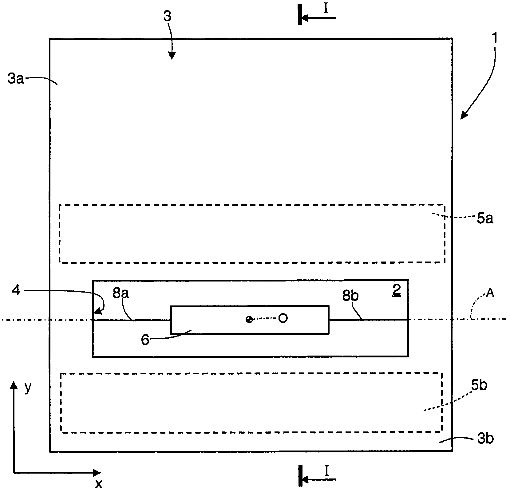
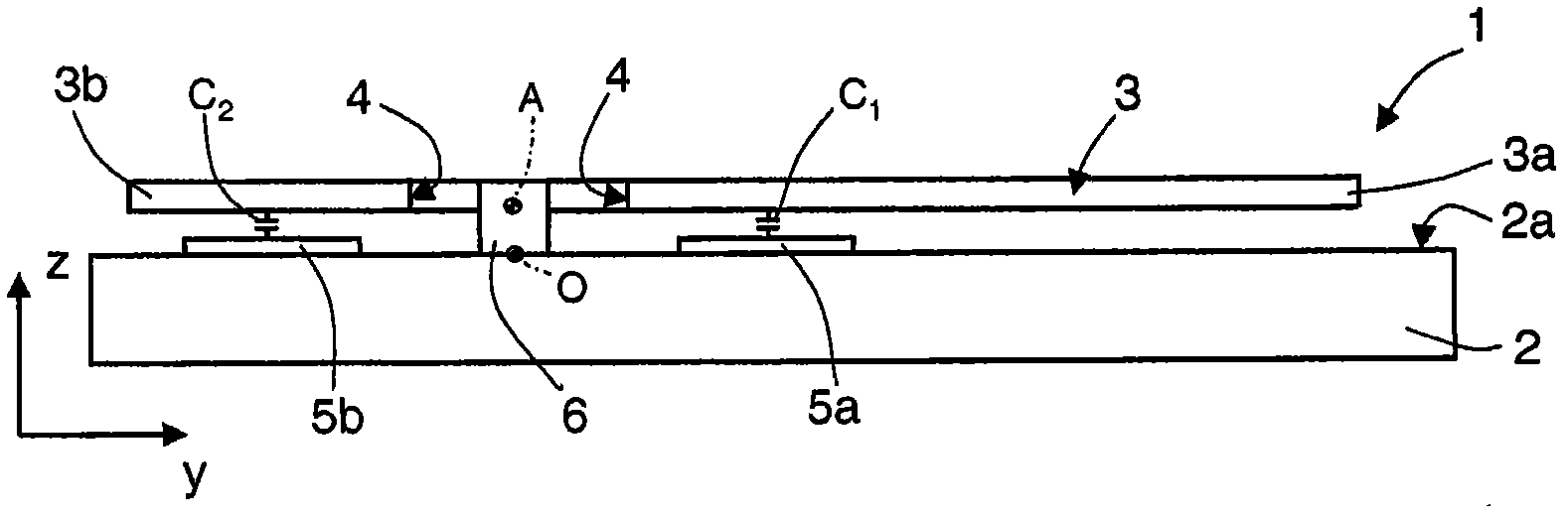
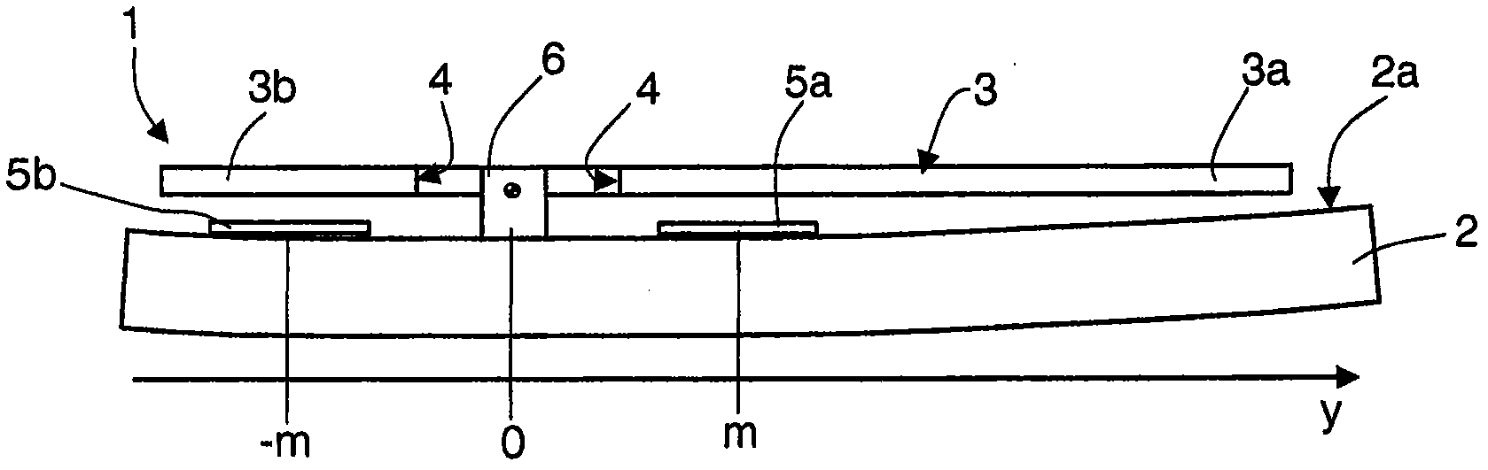
[0034] As will be detailed below, one aspect of the present invention contemplates a suitable modification of the structure of the mechanical coupling (by anchoring or support) of the sensing mass to the substrate of the MEMS structure such that: Due to the induced deformation of the substrate, the sensing mass will experience a displacement substantially in line with the displacement experienced by the fixed electrodes, thus the change in the average gap between the sensing mass and the fixed electrodes (and the associated change in capacitance value) Doesn't happen (or very little). In this way, it is possible to eliminate (or significantly reduce) any thermal drift of the sensor and associated measurement errors, even in the presence of substrate deformation. In particular, the sensing mass is coupled to the substrate by constraining points located at positions corresponding to the fixed electrodes in such a way that the displacement (in the orthogonal direction z) at the p...


PUM


Abstract

The invention discloses a microelectromechanical z-axis detection structure with low thermal drifts. A MEMS detection structure is provided with: a substrate having a top surface, on which a first fixed-electrode arrangement is set; a sensing mass, extending in a plane and suspended above the substrate and above the first fixed-electrode arrangement at a separation distance; and connection elastic elements that support the sensing mass so that it is free to rotate out of the plane about an axis of rotation, modifying the separation distance, as a function of a quantity to be detected along an axis orthogonal to the plane. The MEMS detection structure also includes: a coupling mass, suspended above the substrate and connected to the sensing mass via the connection elastic elements; and an anchoring arrangement.

Description

technical field [0001] The present invention relates to a micro-electromechanical (MEMS) z-axis detection structure with low thermal drift; in particular, it will be explicitly referred to a micro-electromechanical z-axis accelerometer hereinafter, but this is not meant to lose any generality. Background technique [0002] Z-axis inertial accelerometers of the MEMS type are well known and comprise a microelectromechanical structure sensitive to accelerations acting in a direction orthogonal to its main plane of extension and towards the top surface of the corresponding substrate (which It is also possible to detect more accelerations acting in the same plane). [0003] Figure 1a and Figure 1b There is shown a MEMS structure of a z-axis inertial accelerometer of known type, generally designated with reference numeral 1, which further comprises an electronic readout interface (not shown) electrically coupled to the MEMS structure. [0004] The MEMS structure 1 comprises a ...

Claims


Application Information

Patent Timeline
IPC IPC(8): B81B3/00G01P15/125G01C19/56
CPCG01C19/5755G01C19/5769G01P15/02G01P15/125G01C19/5712G01P2015/0831
Inventor G·卡扎尼加L·科罗纳托B·希莫尼
Owner STMICROELECTRONICS SRL
Why Eureka
Try Eureka