AI technical title is built by Patsnap AI team. It summarizes the technical point description of the patent document.
A tool, a technology for protecting materials, applied in textiles, textiles and papermaking, knitting, etc., can solve problems such as damage
Active Publication Date: 2014-11-26
GROZ BECKERT KG
View PDF6 Cites 0 Cited by
Summary
Abstract
Description
Claims
Application Information
AI Technical Summary
This helps you quickly interpret patents by identifying the three key elements:
Problems solved by technology
Method used
Benefits of technology
Problems solved by technology
However, while knitting tools are kept inside the block, they can also be damaged by outside disturbances
Method used
Image
Click on the blue label to locate the original text in one second.
Reading with bidirectional positioning of images and text.
Examples
Embodiment Construction
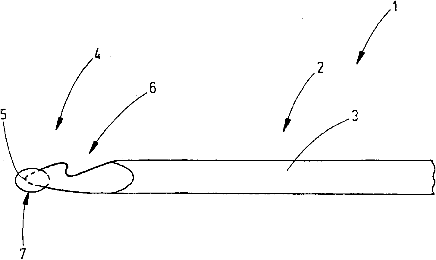
[0022] Attached figure 1 A representative embodiment of the textile tool 1, namely the details of the knitting needle 2 is shown. However, the term "textile tool" 1 is understood to be any common tool used in the textile industry to act on threads or materials made of threads. In this sense, textile tools are especially: knitting needles, for example, latch needles or slider needles or non-tongue knitting needles; sewing needles; trocar needles; felting needles; tufting needles; loop catchers; tufting Blade; heald; sheet; or similar.
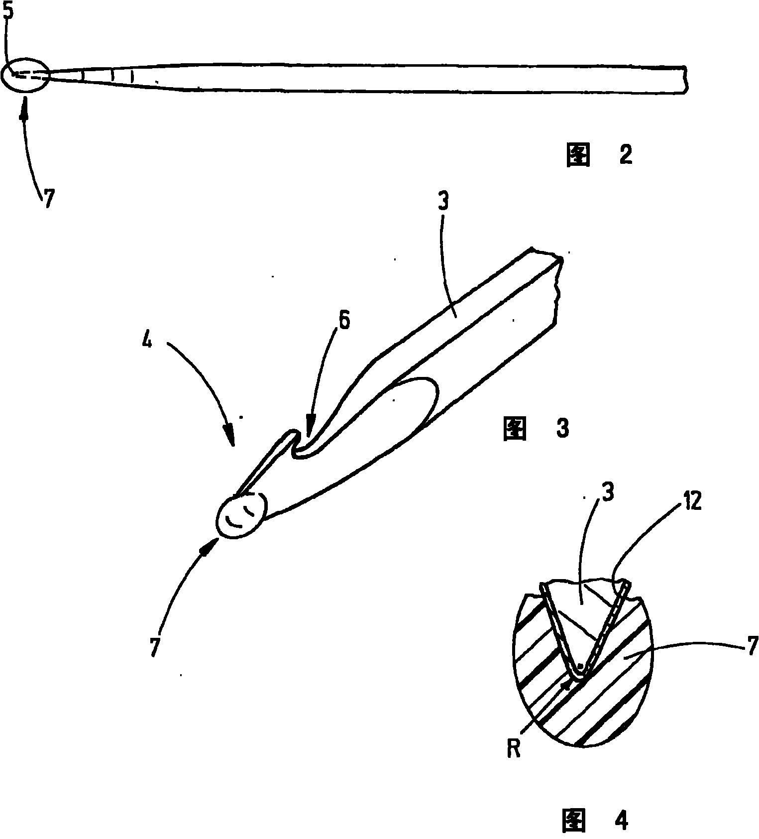
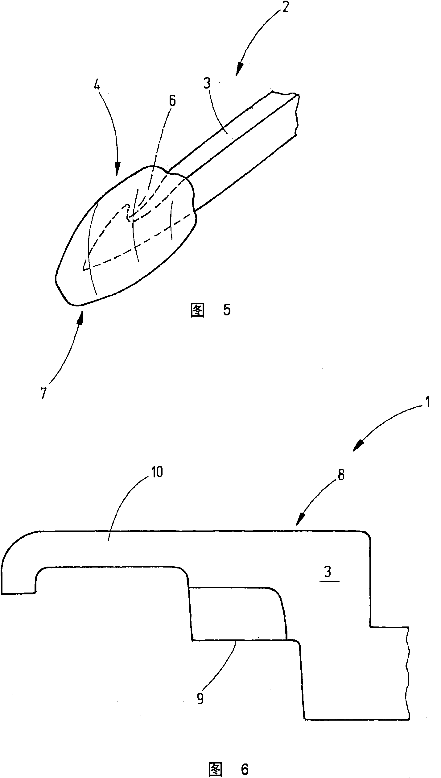
[0023] The knitting needle 2 has a body 3 preferably made of steel. At the end 4 arranged to act on textile materials and threads and therefore represent the working part, the main body 3 has a tip 5, whereby a hook 6 can be provided in the vicinity of said tip. At least in the area of the tip 5, but preferably on all the ends 4 or on the larger surface of the main body 3 or on the entire surface of the main body, the main body 3 is provided wi...
PUM
Abstract
The tool has a body (3) at which a working section (4) e.g. machined part of working needle or head of needle or edge of loop gripper, is formed. A wear protection layer i.e. chromium layer, is provided at the working section. A cover (7) made of removable shock-absorbing protective mass e.g. plastic or thermoplastic hot-dip coating or thick-layer coating, is attached to the working section. The machined part comprises hooks (6) and a locking element i.e. slider. The cover is a coil provided along an edge of the loop gripper.
Description
Technical field [0001] The invention relates to a textile tool which has a tip or a cutting edge or a loop forming part. Background technique [0002] Textile tools usually have very fine structures, such as, in particular, tips, cutting edges, hooks, tongues, and the like, so these structures need to be particularly stable. For example, their stability can be achieved by a suitable anti-wear layer spread over the tips, hooks, tongues or cutting edges of textile tools. In particular, any anti-wear layer, such as a chromium layer, a metal layer, a hard material layer, etc., provides high wear resistance. Although these anti-wear layers therefore provide textile tools with increased stability, they may still unexpectedly increase the sensitivity of textile tools to abnormal stresses. For example, when subjected to abnormal stress, such as collision or vibration, or contact with other hard objects, especially in areas with strong curvature, such as tips, needle hooks or cutting ed...
Claims
Application Information
Patent Timeline
Application Date:The date an application was filed.
Publication Date:The date a patent or application was officially published.
First Publication Date:The earliest publication date of a patent with the same application number.
Issue Date:Publication date of the patent grant document.
PCT Entry Date:The Entry date of PCT National Phase.
Estimated Expiry Date:The statutory expiry date of a patent right according to the Patent Law, and it is the longest term of protection that the patent right can achieve without the termination of the patent right due to other reasons(Term extension factor has been taken into account ).
Invalid Date:Actual expiry date is based on effective date or publication date of legal transaction data of invalid patent.

