Electric connector and wire connecting method thereof

A technology of electrical connectors and connection methods, which is applied in the direction of conductive connection, connection, connection insulation, etc., can solve the problems of affecting signal transmission, unsightly appearance, scrapped cables, etc. The effect of easy welding operation

Active Publication Date: 2011-03-23
深圳市研祥智慧科技股份有限公司
View PDF0 Cites 19 Cited by
  • Summary
  • Abstract
  • Description
  • Claims
  • Application Information

AI Technical Summary

Problems solved by technology

The wire made in this way is not only unattractive in appearance, but also because the wire core itself is slender and has a large number of welding wires, it needs to be bent repeatedly during use and is easy to break. scrapped

Method used


Image

  • Electric connector and wire connecting method thereof
  • Electric connector and wire connecting method thereof
  • Electric connector and wire connecting method thereof

Examples


Embodiment 1

[0033] Embodiment 1. This embodiment takes the metal circular electrical connector (aviation head) as an example to describe the connection method of the electrical connector wire in detail:

[0034] First, the connection method of the aviation socket wire:

[0035] 1. Before welding, each wire is marked with a pointed or columnar copper or nickel-plated terminal, with a length of 3-4MM; choose a similar large heat shrinkable sleeve according to its installation diameter, and the length of the large heat shrinkable sleeve is about 35-45MM. cable through.

[0036] 2. Before each wire is welded, put a small heat-shrinkable sleeve one by one, and the pins of the wire and the aviation socket are welded according to the design requirements.

[0037] 3. Put the large heat-shrinkable sleeve on the aviation socket, preheat the hot-melt glue gun to 220°C, insert it into the root of the welding, and inject an appropriate amount of hot-melt glue to cover the solder joint. The root tube ...

Embodiment 2

[0046] Embodiment 2. In this embodiment, the structure of the electrical connector is described in detail by taking the metal circular electrical connector (aviation connector) as an example.

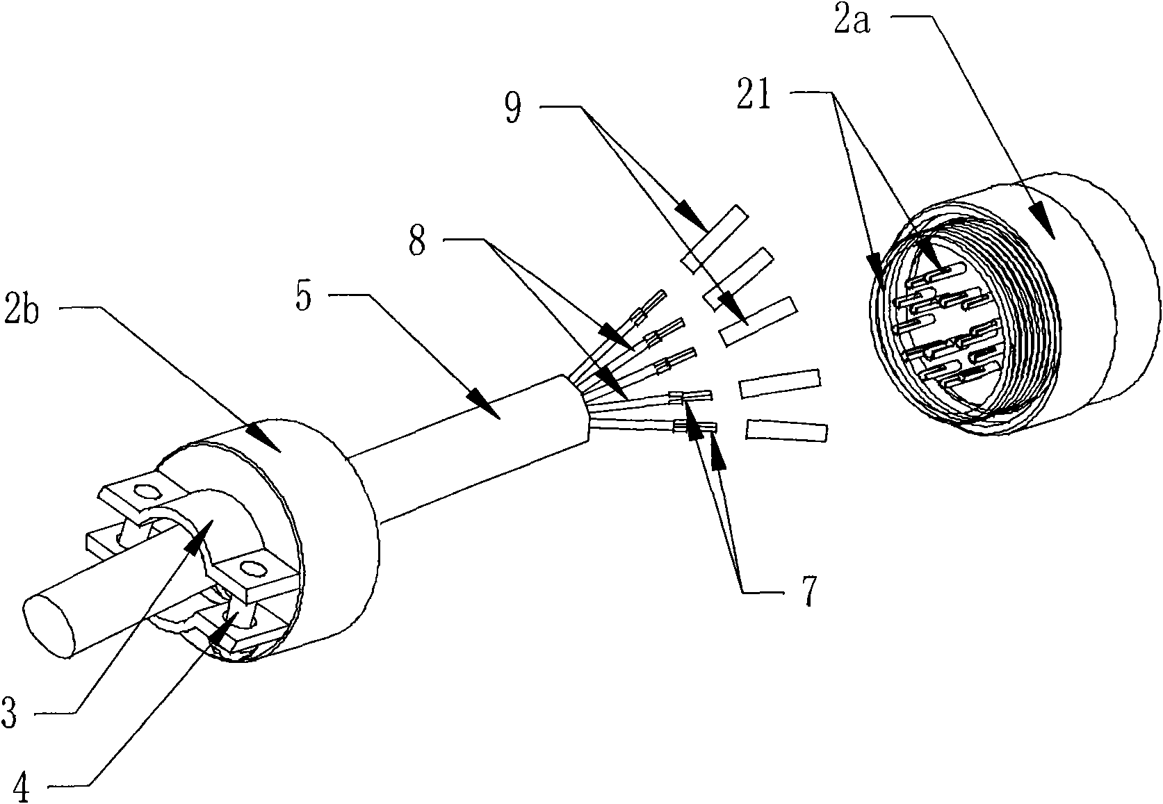
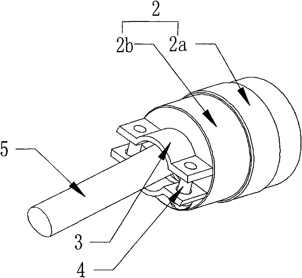
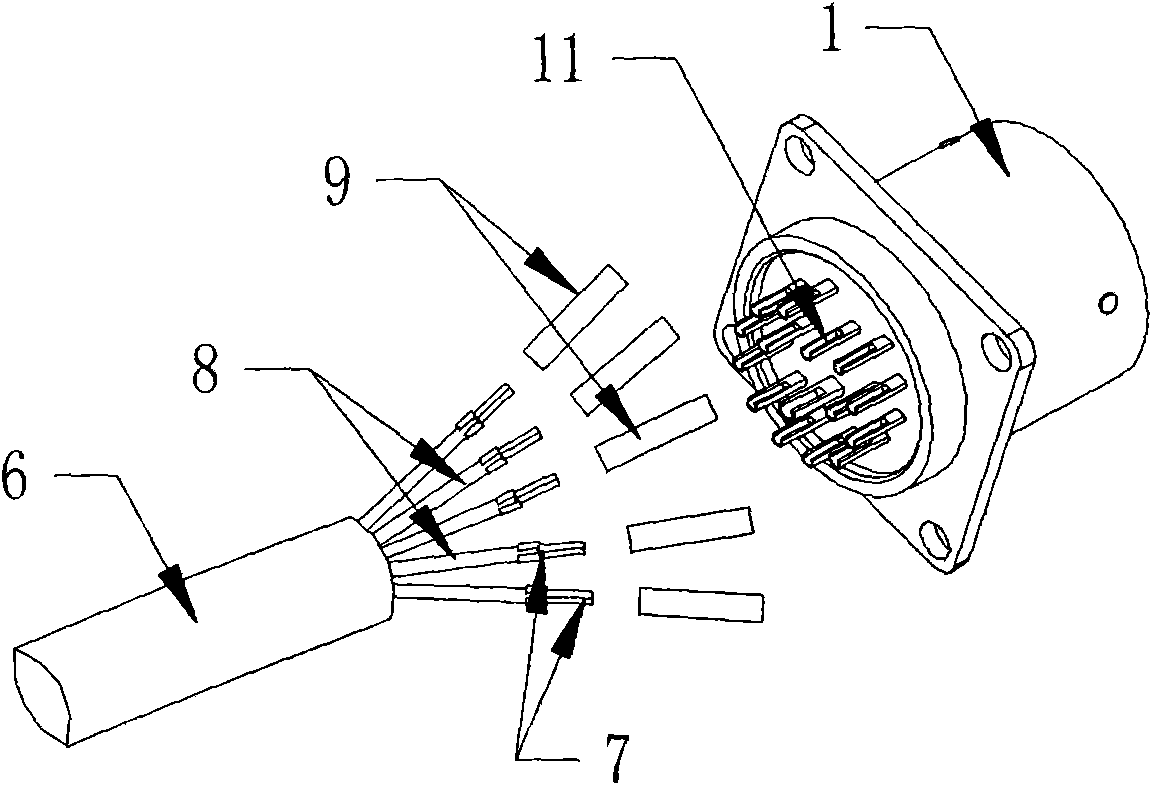
[0047] Such as figure 1 , 2 , 3, and 4, an electrical connector includes a socket 1, a plug 2 with a tail clip 3, a first cable 5 connected to the plug 2, and a second cable 6 connected to the socket 1. Both the first cable 5 and the second cable 6 are respectively composed of a plurality of wires 8 , and a metal terminal 7 is fixed at the end of each wire 8 .

[0048] Such as figure 1 , 2 Shown is the connection structure of plug 2 (aviation plug). The plug 2 includes a plug body 2a, a rear cover 2b screwed to the plug body 2a, a tail clip 3 is provided at the rear of the rear cover 2b, and a metal terminal 7 on each wire 8 of the first cable 5 is connected to a metal terminal 7 on the plug body 2a. The pins 21 are welded together, each wire 8 is covered with a small heat-shrinkab...


PUM


Abstract

The invention discloses an electric connector and a wire connecting method thereof. The connecting method comprises the step of connecting socket wires or plug wires and comprises the following concrete steps: strengthening the end parts of wires; welding and protecting each wire after the end parts of the wires are welded with a socket or a plug; and protecting the integrated wires connected with the socket or the plug. The electric connector comprises a socket, a plug, a first wire cable and a second wire cable, wherein the first wire cable and the second wire cable are respectively connected with the plug or the socket; metal terminals are fixed at the end parts of the wires and are welded together with pins on the plug or the socket; a small thermal shrinkable sleeve is sleeved at thewelding part of the wires; a big thermal shrinkable sleeve is sleeved outside the second wire cable; and the sheath of the first wire cable is clamped by a tail clamp of the plug. The connecting method of the invention can enhance the connecting strength, can enhance the tensile resistance and the torsion resistance, and completely can ensure the reliability requirement of a reinforced computer. The electric connector of the invention has high connecting strength, tensile resistance and torsion resistance, and the wires can not be broken easily.

Description

technical field [0001] The invention relates to a connector, in particular to an electrical connector and a wire connecting method of the electrical connector. Background technique [0002] In the field of military industry, at present, the requirements for the reliability of wire rods of reinforced computers far exceed the requirements of general industrial computers. Therefore, the I / O function input and output of this type of computers generally abandon the VGA, PS / 2, LPT, COM, LAN and other international standard interfaces are replaced by circular electrical connectors as transfers, and among them, welding circular electrical connectors are the most commonly used because of their relatively low price and moderate performance. However, in the manufacturing method of this type of welding circular electrical connector wire, generally only the welding method of stripping the wire and covering the thin heat-shrinkable tube is used. The wire made in this way is not only unat...

Claims


Application Information

Patent Timeline
Patent Type & Authority Applications(China)
IPC IPC(8): H01R43/00H01R43/02H01R4/02H01R4/72H01R9/03
Inventor 李运峰
Owner 深圳市研祥智慧科技股份有限公司
Why Eureka
Try Eureka