
Air pressure type base frequency-adjusted electronic artificial throat

A pneumatic and artificial throat technology, applied in the field of electronic artificial throat, can solve the problems of obvious machine smell, complicated mechanism, lack of tone change, etc.

Inactive Publication Date: 2011-03-30
BEIHANG UNIV +1
View PDF1 Cites 10 Cited by
  • Summary
  • Abstract
  • Description
  • Claims
  • Application Information

AI Technical Summary

Problems solved by technology

The current electronic artificial larynx has many shortcomings such as lack of voice change, especially the lack of tone change, obvious machine smell, and large background noise.
[0003] In order to improve the pronunciation effect, the current researchers focus on the removal of the background noise of the electronic artificial laryngeal, and the control of the electronic artificial laryngeal pulse generation through EMG and other signals. Due to the complexity of the EMG signal generation and analysis, The effect is not ideal
Some researchers use the collection and analysis of voice signals, image signals and noise signals to regulate the voice of electronic artificial laryngeal, the mechanism is complicated, the cost is increased, and the reliability is low
Based on the limitations of currently existing electronic laryngo technology, the pitch of the voice produced by the electronic artificial larynx does not change throughout the speaking process, which is the main reason for the difference in the quality of the voice of the electronic artificial larynx and the normal voice

Method used


Image

  • Air pressure type base frequency-adjusted electronic artificial throat
  • Air pressure type base frequency-adjusted electronic artificial throat
  • Air pressure type base frequency-adjusted electronic artificial throat

Examples


Embodiment Construction

[0040] Embodiments of the present invention will be described in detail below in conjunction with the accompanying drawings.

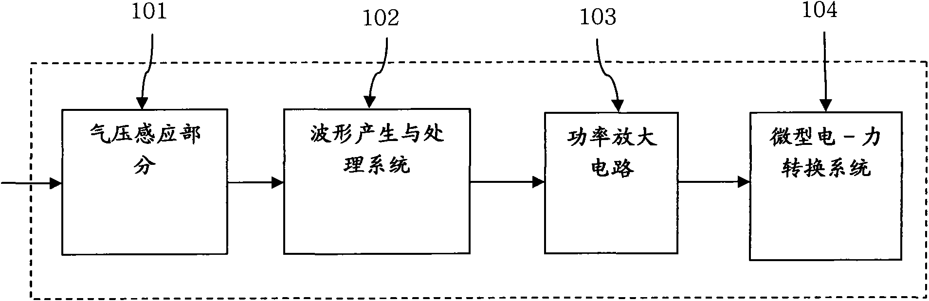
[0041] figure 1 It is a composition diagram of a glottal wave analog electronic artificial laryngeal with personal characteristics according to an embodiment of the present invention. The electronic artificial larynge includes an air pressure sensing part 101, a waveform generation and processing system 102, a power amplifier circuit 103, a microelectronic Force conversion system 104 .

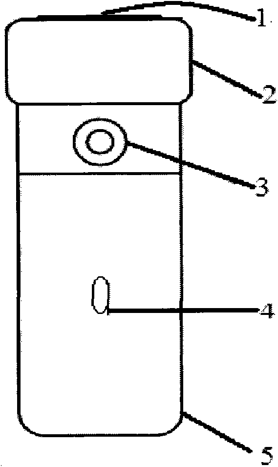
[0042] According to a specific embodiment, the air pressure sensing part 101 includes a pressure sensor 11, such as Figure 5 As shown, the sensor 11 can convert the air pressure signal in an air mask 12 at a fistula 13 in the user's throat into an electrical signal, and the air pressure will determine the amplitude of the electrical signal. The electrical signal needs to be input to the air pressure signal receiving module 14 ( Image 6 ); the output of the air pre...


PUM


Abstract

The invention discloses an air pressure type base frequency-adjusted electronic artificial throat, which is characterized in that: an air hood is arranged outside a throat fistula and the air pressure inside the gas hood is detected; and the base frequency of a glottal wave is controlled according to a pneumatic signal so as to change the voice tone. The air pressure type base frequency-adjusted electronic artificial throat comprises an air pressure sensing part (101), a waveform generating and processing part (102), a power amplifier circuit (103) and a miniature electricity-force conversionpart (104), wherein the pneumatic sensing part (101) is used for detecting the air pressure outside a throat fistula of a patient and generating an air pressure detection signal; the waveform generating and processing part (102) is used for generating a glottal wave signal so as to change the base frequency according to the air pressure detection signal; the power amplifier circuit (103) amplifies the glottal wave signal; and the miniature electricity-force conversion part (104) generates vibration under the driving of the glottal wave signal. The vibration is applied to the neck of the patient to generate the glottal wave signal, and the glottal wave signal is modulated by the tongue, the nasal cavity, the oral cavity, the lips and other organs of the patient to form voice outside the lips.

Description

technical field [0001] The invention belongs to the field of voice rehabilitation for voice-deficit patients, and relates to an electronic artificial larynx with pneumatic fundamental frequency adjustment. Background technique [0002] Among the various means used by human beings to communicate, voice is the most basic, effective and important one. At present, there are hundreds of thousands of patients with laryngeal cancer and other serious laryngeal diseases in the world. In order to treat laryngeal diseases, laryngectomy has to be performed. For some patients with severe laryngeal diseases, total laryngectomy must be performed. After the operation, the patient completely loses the ability to speak, and thus loses the ability to use voice for language communication. During total laryngectomy, a tracheostomy is usually used for postoperative breathing of the patient. After total laryngectomy, patients mostly rely on electronic artificial larynx for vocalization. Electron...

Claims


Application Information

Patent Timeline
IPC IPC(8): A61F2/50A61F2/68
Inventor 牛海军李立峰樊瑜波邵晓宁王喜太
Owner BEIHANG UNIV
Learn More