Discharging device of carding machine

A carding machine and carding technology, used in deburring devices, textiles and papermaking, fiber processing, etc., can solve problems such as high operating costs, low production efficiency, and damage to the length of the fluff, and enhance the ability to obtain fluff. The strength is not easy to break, and the effect of reducing the damage to the length of the fluff

Active Publication Date: 2011-03-30
HANGZHOU YUANDESHAN SCI & TECHNICAL CO LT
View PDF1 Cites 0 Cited by
  • Summary
  • Abstract
  • Description
  • Claims
  • Application Information

AI Technical Summary

Problems solved by technology

Because the surface of the high-speed stripping roller carries high-speed airflow when it rotates at high speed, this high-speed airflow will be turbulent after being blocked in the fairing with four walls as flat, and the fluff thrown out by the high-speed stripping roller at high speed is also in a disordered state. Then it is absorbed by the dust cage with negative pressure inside, and the fluff adsorbed on the surface of the dust cage is also chaotic, it is not easy to form a uniform wool net, the strength of the strip is low, and the strip is easy to break
Due to the turbulent airflow inside the fairing, the dust cage has a weak ability to absorb fluff, and some fluff is brought back by the high-speed peeling roller to form falling objects, which seriously affects the product extraction rate
Usually, it is necessary to recycle the fallen objects, resulting in low production efficiency and increased damage to the length of the fluff.
Also, due to the turbulence of the airflow inside the fairing, the dust cage needs a large negative pressure to absorb the fluff, which will increase the power of the equipment, resulting in the disadvantages of high energy consumption and high operating costs.

Method used


Image

  • Discharging device of carding machine
  • Discharging device of carding machine
  • Discharging device of carding machine

Examples


Embodiment Construction

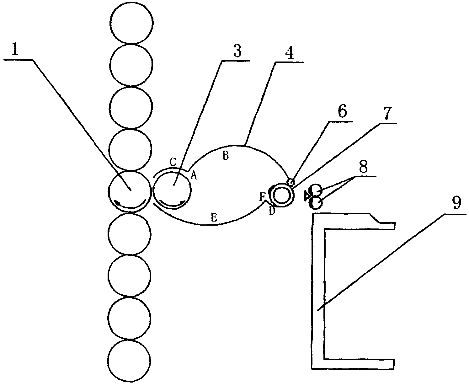
[0021] figure 1 The structure of one embodiment of the present invention is shown.

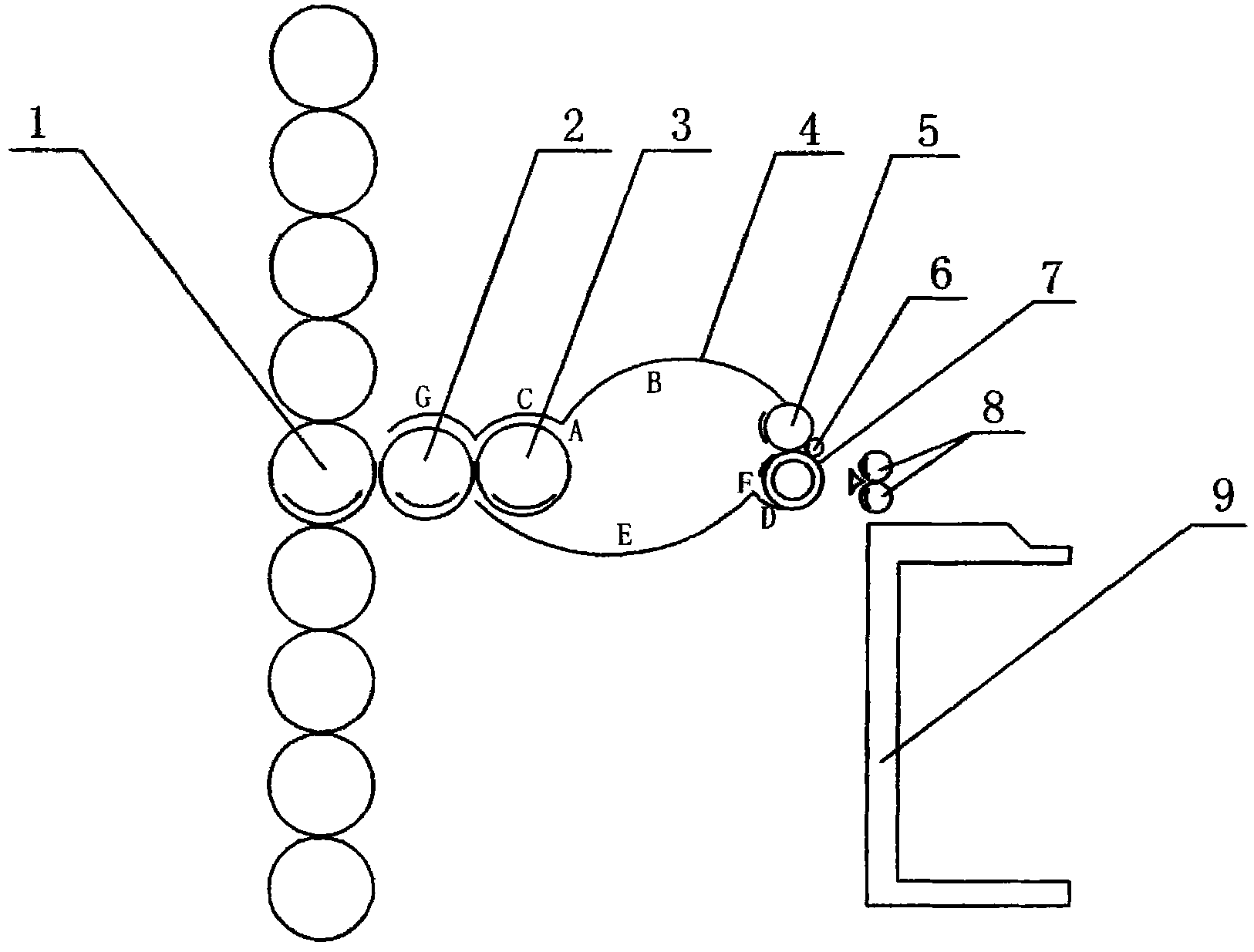
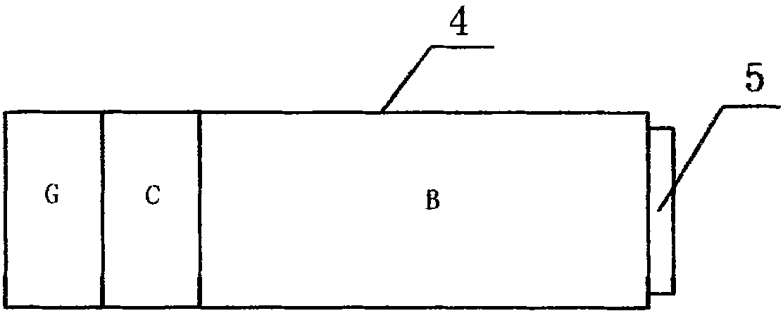
[0022] like figure 1 As shown, the machine discharge device according to one embodiment of the present invention includes a fairing 4 , a high-speed depilling roller 3 and a dust cage 7 . The high-speed stripping roller 3 is set adjacent to the central carding roller 1 of the carding machine, and is used to strip the fluff combed on the central carding roller 1, and throw the fluff into the fairing 4 by the centrifugal force of high-speed rotation . Fairing 4 is made up of upper wall B, lower wall E and two side walls, is used for closing the space between described high-speed depilling roller 3 and dust cage 7. And the dust cage 7 is used for absorbing the fluff in the fairing 4 .

[0023] The fairing 4 is located between the high-speed depilling roller 3 and the dust cage 7, and includes four walls. The upper wall B of the fairing 4 is a curved surface protruding upward, the lower wall ...


PUM


Abstract

The invention discloses a discharging device of a carding machine. The device comprises a high-speed wiper roll (3), a fairing (4) and a dust cage (7), wherein the upper wall (B) of the fairing (4) is an upwards protruded curved surface while the lower wall (E) is a downwards protruded curved surface; both of the two side walls of the fairing (4) are planes; a low-speed doffer (5) is arranged between one end of the upper wall (B) and the dust cage (7); the axis of the low-speed doffer (5) is parallel to that of the dust cage (7); and the low-speed doffer (5) is arranged adjacently to the dust cage (7). The discharging device overcomes the disadvantages in the prior art, solves the technical problems which are not solved for a long time in the field, obviously improves the carding effect, can card high-quality fluff, improves the economic benefit of a product, can reduce the carding cost and brings brilliant progress technologically.

Description

technical field [0001] The invention relates to the technical field of textile raw material preparation equipment, in particular to an outlet device of a carding machine. Background technique [0002] In the exiting device of the existing carding machine, the high-speed stripping roller is directly adjacent to the carding roller or the Xilin and the needle direction is in parallel with the stripping action. Fairing with planar rectangular cavity structure. Because the surface of the high-speed stripping roller carries high-speed airflow when it rotates at high speed, this high-speed airflow will be turbulent after being blocked in the fairing with four walls as flat, and the fluff thrown out by the high-speed stripping roller at high speed is also in a disordered state. Then it is absorbed by the dust cage with negative pressure inside, and the fluff adsorbed on the surface of the dust cage is also chaotic, and it is not easy to form a uniform wool net. The strength of the ...

Claims


Application Information

Patent Timeline
Patent Type & Authority Applications(China)
IPC IPC(8): D01G15/14D01G15/26D01G15/46D01G15/50
Inventor 黄金山
Owner HANGZHOU YUANDESHAN SCI & TECHNICAL CO LT
Why Eureka
Try Eureka