Intelligent broadcast monitoring system
A monitoring system and subsystem technology, applied in the field of electronic communication, can solve difficult tasks such as launch pad tasks
- Summary
- Abstract
- Description
- Claims
- Application Information
AI Technical Summary
Problems solved by technology
Method used
Image
Examples
Embodiment 1
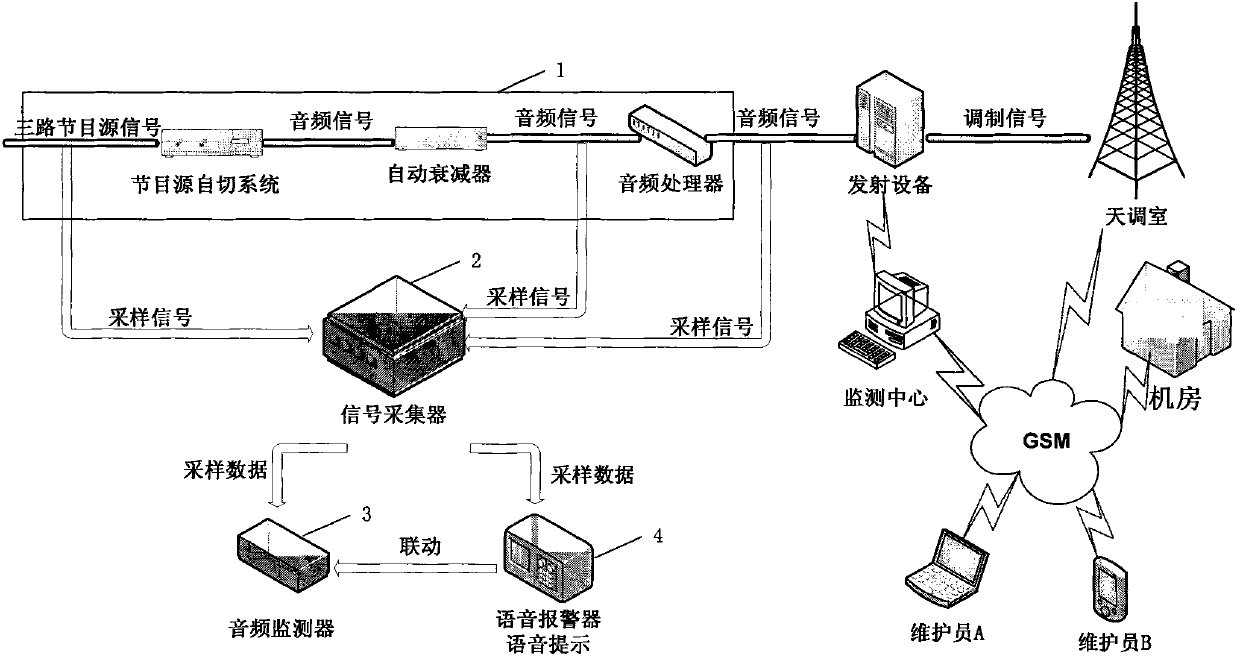
[0084] see figure 1 , The present invention discloses an intelligent broadcast control monitoring system, said system includes: an audio signal subsystem 1, a signal acquisition subsystem 2, a broadcast monitoring subsystem 3, an alarm subsystem 4, and a monitoring center subsystem.
[0085] The signal acquisition subsystem 2 is connected with the audio signal subsystem 1, the broadcast monitoring subsystem 3, and the alarm subsystem 4 respectively, and collects the sampling signal that the audio signal subsystem 1 sends; the broadcast monitoring subsystem 3 and the signal acquisition subsystem 2 are connected to monitor the sampling signal collected by the signal acquisition subsystem 2; the alarm subsystem 4 is connected with the broadcast monitoring subsystem 3, and the broadcast monitoring subsystem 3
[0086] When an abnormality is detected, the corresponding alarm information is issued by comparing the alarm methods by category, and at the same time an alarm signal is se...
Embodiment 2
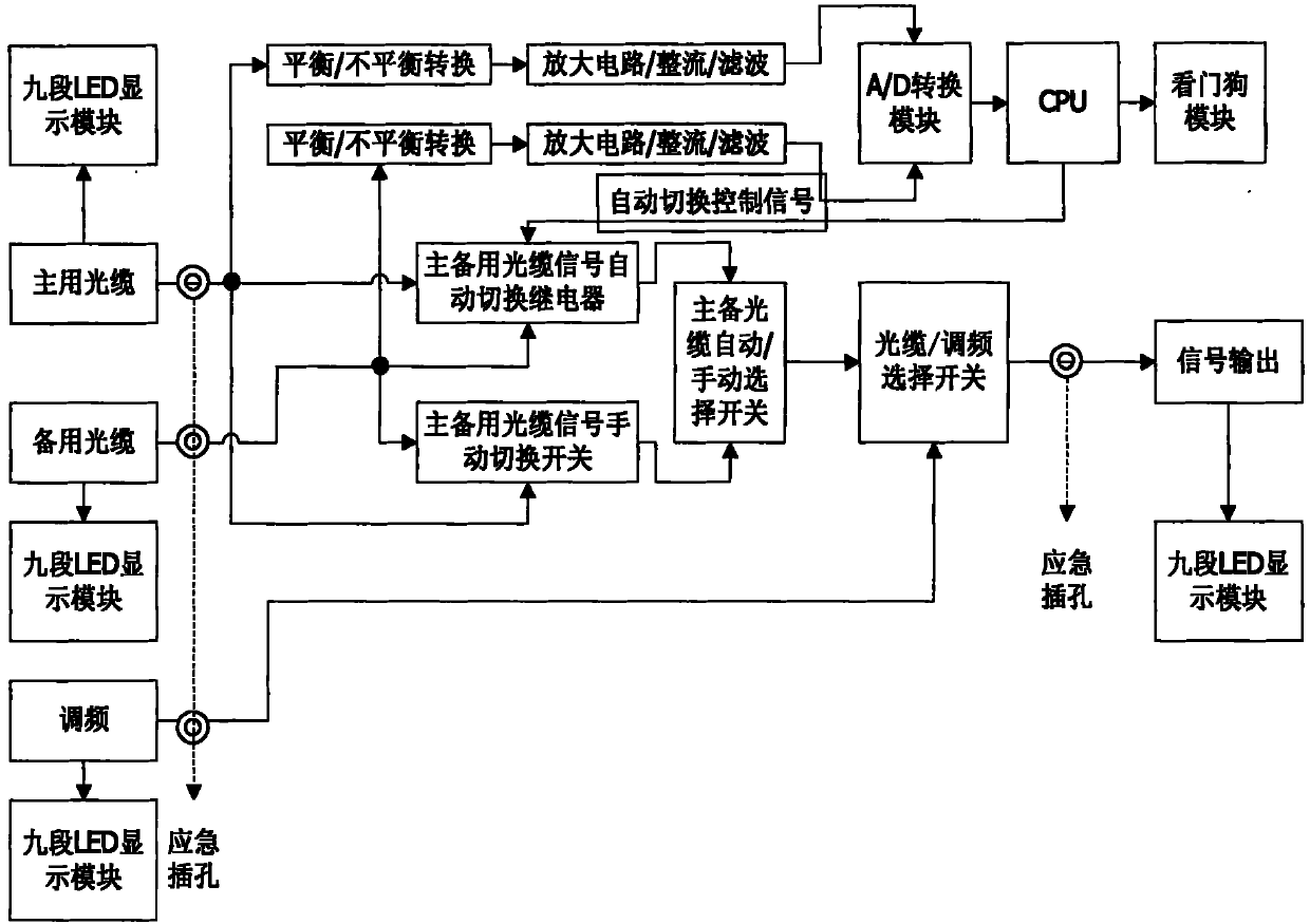
[0160] In this embodiment, the difference between this embodiment and Embodiment 1 lies in the program source switcher of the audio signal subsystem 1 .
[0161] In this embodiment, the function of the program source switcher is as follows:
[0162] 1. Automatic or manual signal switching mode is adopted between the main SDH1 (HARRIS) optical cable program source signal and the backup SDH2 (MA05) optical cable program source signal. The default position of the device is in the automatic switching mode. When the signal of the main SDH1 (HARRIS) optical cable program source is interrupted, and the standby SDH2 (MA05) optical cable program source still has the signal, the automatic switching operation will be implemented. The automatic switching time is 3 seconds. When the automatic switching fails, the two optical cable signals can also be switched manually.
[0163] 2. Due to the poor quality of the FM signal, there is a lot of noise, which is not conducive to the judgment of...
Embodiment 3
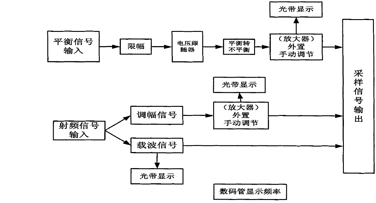
[0202] In this embodiment, the difference between this embodiment and Embodiment 1 lies in the signal acquisition subsystem of the system. see image 3 , in this embodiment, the signal acquisition subsystem includes the following modules:
[0203] 1. Limiting module:
[0204] In order to prevent the peak-to-peak value of the collected signal from being too large to damage the subsequent digital integrated circuit, it is necessary to limit the collected signal. The function of the limiter circuit is to limit the output signal amplitude within a certain range, that is, when the input voltage exceeds a certain reference range, the output voltage will be limited to a certain level (called limiter level), and no longer Varies with input voltage. Use clamping diodes to ensure that the amplitude of the audio input signal does not exceed ±12V; the function of the clamping circuit is to keep the top or bottom of the periodically changing waveform at a certain DC level.
[0205] 2. ...
PUM
 Abstract
Description
Claims
Application Information
 - R&D
- Intellectual Property
- Life Sciences
- Materials
- Tech Scout
- Unparalleled Data Quality
- Higher Quality Content
- 60% Fewer Hallucinations
Browse by: Latest US Patents, China's latest patents, Technical Efficacy Thesaurus, Application Domain, Technology Topic, Popular Technical Reports.
© 2025 PatSnap. All rights reserved.Legal|Privacy policy|Modern Slavery Act Transparency Statement|Sitemap|About US| Contact US: help@patsnap.com


