
Light-emitting device

A technology for light-emitting devices and light-emitting elements, which is applied to electrical components, electric solid-state devices, circuits, etc., can solve the problems of uneven temperature distribution of light-emitting element groups, easy reduction of light-emitting efficiency, reliability and lifespan, etc., so as to improve the light-emitting efficiency and Effectiveness of reliability, simplification of structure, and suppression of deterioration

Active Publication Date: 2011-03-30
PANASONIC CORP
View PDF2 Cites 5 Cited by
  • Summary
  • Abstract
  • Description
  • Claims
  • Application Information

AI Technical Summary

Problems solved by technology

[0004] However, this mounting substrate 100 has a structure in which one light-emitting element 101 is mounted in the cavity 110. Although the heat dissipation of each light-emitting element 101 is improved, when using such a mounting substrate 100 to arrange a plurality of light-emitting elements 101 closely When viewed as a whole of the light-emitting element group, similar to the above, the temperature distribution of the light-emitting element group becomes uneven, and the temperature of the light-emitting element in the central part becomes high under the influence of heat from the peripheral part, and the luminous efficiency, reliability, and life are likely to decrease.

Method used


Image

  • Light-emitting device
  • Light-emitting device
  • Light-emitting device

Examples


Embodiment Construction

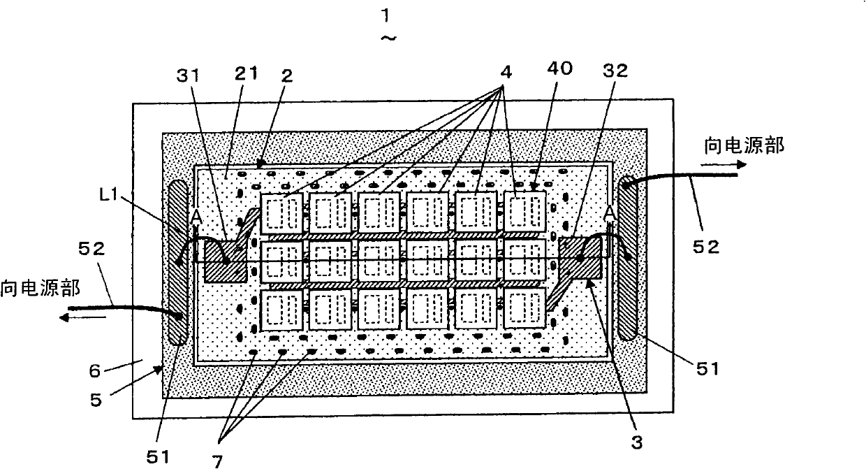
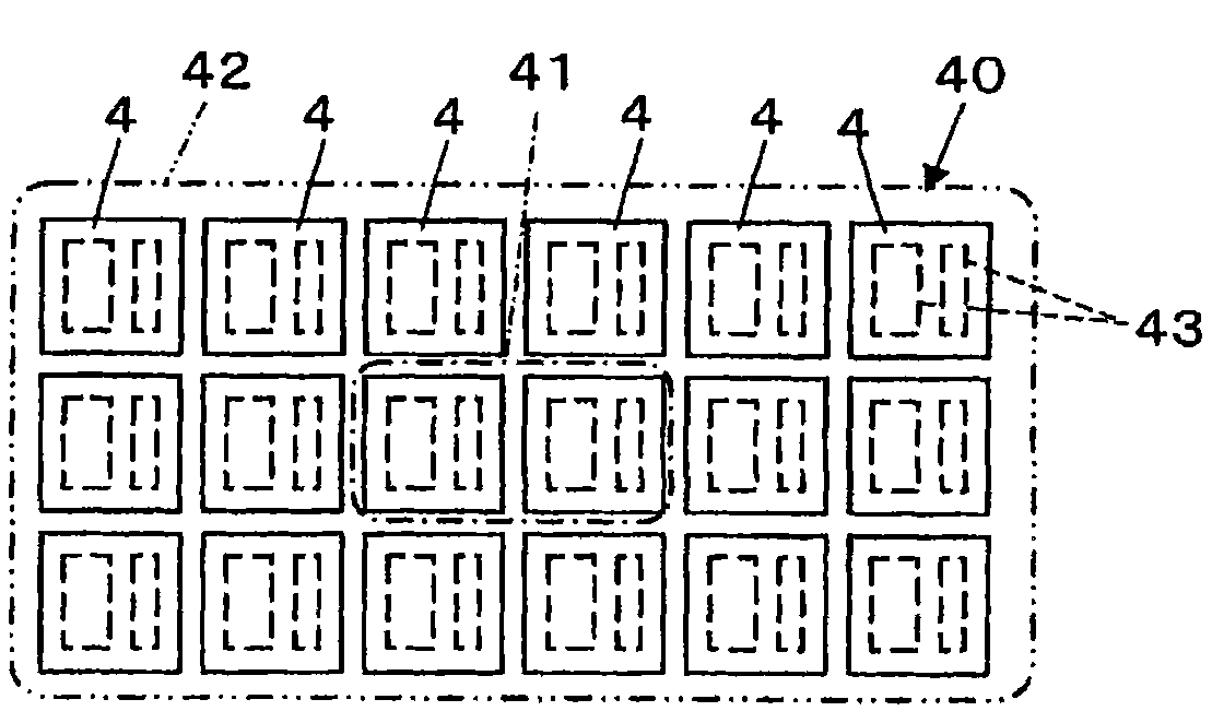
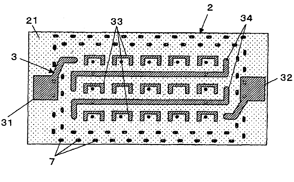
[0032] Below, refer to Figure 1 to Figure 4 A light emitting device according to a first embodiment of the present invention will be described. figure 1 Showing the structure of the light emitting device 1 of this embodiment, figure 2 shows the arrangement structure of the light emitting element group 40 of the light emitting device 1, image 3 A wiring pattern on the mounting substrate 2 of the light emitting device 1 is shown. The light emitting device 1 includes an insulating mounting substrate 2, a wiring pattern 3 mounted on the element mounting surface 21 of the mounting substrate 2, and a plurality of (here, 18) light emitting elements 4 mounted on the wiring pattern 3. The light-emitting element group 40 constituted, the frame-shaped wiring board 5 for supplying power to the light-emitting element 4 , and the heat sink 6 for dissipating heat from the mounting board 2 and the wiring board 5 . Mounting board 2 and wiring board 5 are mounted on heat sink 6 .

[003...


PUM


Abstract

The present invention provides a light-emitting device, in the light-emitting device having a light-emitting element group with a plurality of light-emitting elements densely, the temperature distribution of the light-emitting element group is uniformed so as to improve light-emitting efficiency and reliability. The light-emitting device (1) comprises a mounting substrate (2) equipped with a plurality of light-emitting elements, a wiring figure (3) arranged on an element mounting surface (21), a hot passage (7), and a radiating figure (8) crossed with the heat passage (7). The light-emitting element group includes a central group and a perimeter group, the hot passage includes a central passage and a perimeter passage, the radiating figure includes a central radiating figure and a perimeter radiating figure connected to the central passage and the perimeter passage respectively, such that the central passage and the central radiating figure, the perimeter passage and the perimeter radiating figure are not contacted with each other. Thereby, the heat from the perimeter group will not be transferred to the central group, the central group is prevented from high temperature, the temperature distribution of the light-emitting element group is uniformed, and light-emitting efficiency and reliability are all improved.

Description

technical field [0001] The present invention relates to a heat dissipation structure of a light-emitting element group in a light-emitting device having a light-emitting element group densely mounted with a plurality of light-emitting elements. Background technique [0002] Conventionally, there is known a light-emitting device that is mounted on a mounting substrate by connecting a plurality of light-emitting elements in series (for example, refer to Patent Document 1). In such lighting devices, such as Figure 10 As shown in (a), a plurality of light-emitting elements 101 are arranged close to each other, and the element group P in the central part of the light-emitting element group is affected by heat from the element group Q in the peripheral part as shown by the arrow, so the temperature distribution of the light-emitting element group is as follows: Figure 10 As shown in (b), the temperature is high in the central part. At this time, if Figure 10 As shown in (c), th...

Claims


Application Information

Patent Timeline
IPC IPC(8): H01L33/64H01L33/62H01L25/075
CPCH01L2224/16225H01L2224/48091H01L2224/48227H01L2924/00014
Inventor 骑马啓嗣横谷良二
Owner PANASONIC CORP
Learn More