PWM/PFM synchronous control dimming circuit

A control circuit and synchronous control technology, applied in the field of gas discharge lamp dimming circuit, PWM/PFM synchronous control dimming circuit, and can solve the problem of inefficient energy

Inactive Publication Date: 2011-03-30
SHANGHAI XINGDIAO OPTOLECTRONIC LIGHTING TECH
View PDF3 Cites 5 Cited by
  • Summary
  • Abstract
  • Description
  • Claims
  • Application Information

AI Technical Summary

Problems solved by technology

The incandescent lamp is a resistive load. When the lamp voltage changes, the...

Method used


Image

  • PWM/PFM synchronous control dimming circuit
  • PWM/PFM synchronous control dimming circuit
  • PWM/PFM synchronous control dimming circuit

Examples


Embodiment Construction

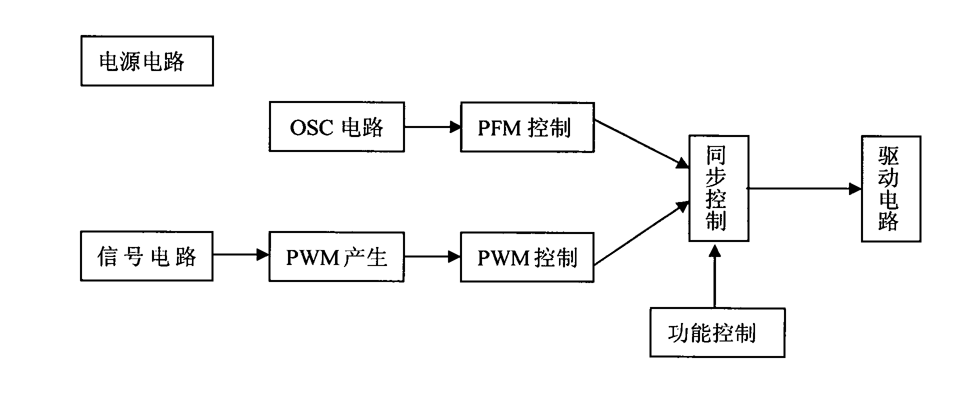
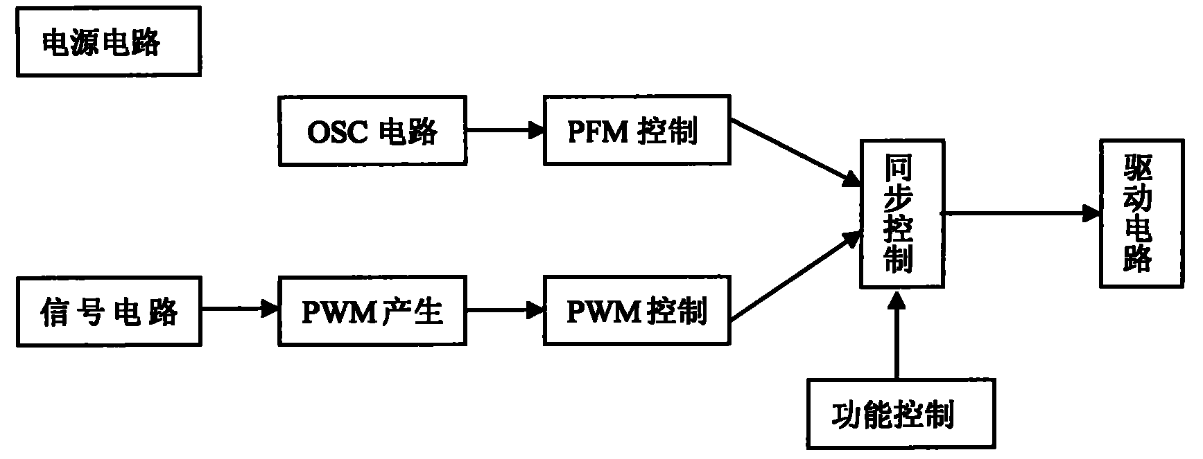
[0014] PWM / PFM synchronous control dimming circuit, including power supply circuit, signal circuit, PWM generation circuit, PWM control circuit, OSC circuit, PFM control circuit, synchronous control circuit, function control circuit and drive circuit

[0015] combined with figure 1 In order to further explain the function of the invented PWM / PFM synchronous control dimming circuit:

[0016] The inside of the power supply circuit is stabilized to generate a precise reference voltage to supply power for all internal unit circuits.

[0017] The oscillating circuit is externally connected with the minimum frequency setting circuit, and the capacitor is charged from the reference source through the PFM circuit. After the capacitor is set, the oscillating frequency is determined by the PFM control circuit charging current to the capacitor, and the frequency is changed through V / F conversion.

[0018] The PWM generation circuit, the reference voltage and the sampling feedback signal...


PUM


Abstract

The invention discloses a PWM/PFM synchronous control dimming circuit, comprising a power supply circuit, a PWM generating circuit, a PWM control circuit, an OSC circuit, a PFM control circuit, a PWM/PEFM synchronous control circuit, a function control circuit and a drive circuit. Linearly changing adjustable circuits of impulse width and impulse frequency are generated synchronously in proportion according to the change requirements of control signals so as to control a dimming control circuit in which the loading reaches to the adjusting power through the drive circuit; and the dimming circuit can be applied to dimming gas discharge lamps such as fluorescent light, high voltage sodium lamp, Metal halogen lamp, and the like, and is applied to electronic field and microelectronic field.

Description

technical field [0001] The invention belongs to the technical field of high-frequency pulse electronics and integrated microelectronics, and relates to a dimming circuit for a gas discharge lamp, in particular to a PWM / PFM synchronous control dimming circuit. technical background [0002] Green lighting is one of the most promising high-tech fields in the 21st century. Green lighting is not only the traditional energy saving and economic benefit improvement, but more importantly, it focuses on the rational use of resources and environmental protection. It meets the needs of lighting quality and visual environment. higher requirements under conditions. [0003] Dimming technology is widely used in incandescent lamps, and a voltage regulation scheme can be used. The incandescent lamp is a resistive load. When the lamp voltage changes, the lamp power and brightness also change, but this dimming method does not save energy. Taking a 25W incandescent bulb as an example, when th...

Claims


Application Information

Patent Timeline
IPC IPC(8): H05B41/38
CPCY02B20/202Y02B20/00
Inventor 汪宗纯
Owner SHANGHAI XINGDIAO OPTOLECTRONIC LIGHTING TECH
Why Eureka
Try Eureka