Punch die ejector for screw heading machine

A technology of screw head machine and ejector device, which is applied in the direction of nuts, ejection equipment, mechanical equipment, etc.

Inactive Publication Date: 2013-01-02
玟旸机械有限公司
View PDF7 Cites 4 Cited by
  • Summary
  • Abstract
  • Description
  • Claims
  • Application Information

AI Technical Summary

Problems solved by technology

[0006] It can be seen that the structure and use of the above-mentioned existing screwheading machines obviously still have inconvenience and defects, and it is easy to cause waste and shutdown during processing problems, and need to be further improved
In order to solve the above-mentioned problems, the relevant manufacturers have tried their best to find a solution, but for a long time no suitable design has been developed, and the general product has no suitable structure to solve the above-mentioned problems. This is obviously the relevant industry. Urgent problem

Method used


Image

  • Punch die ejector for screw heading machine
  • Punch die ejector for screw heading machine
  • Punch die ejector for screw heading machine

Examples


Embodiment Construction

[0074] In order to further explain the technical means and effects of the present invention to achieve the intended purpose of the invention, the specific implementation, structure and characteristics of the die ejector of the screw head machine proposed according to the present invention will be described below in conjunction with the accompanying drawings and preferred embodiments. And its effect, detailed description is as follows.

[0075] The aforementioned and other technical contents, features and effects of the present invention will be clearly presented in the following detailed description of preferred embodiments with reference to the drawings. For convenience of description, in the following embodiments, the same elements are denoted by the same numbers.

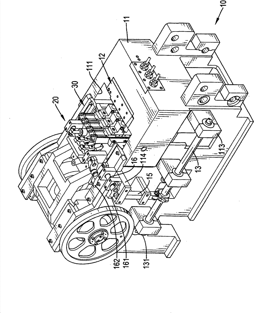
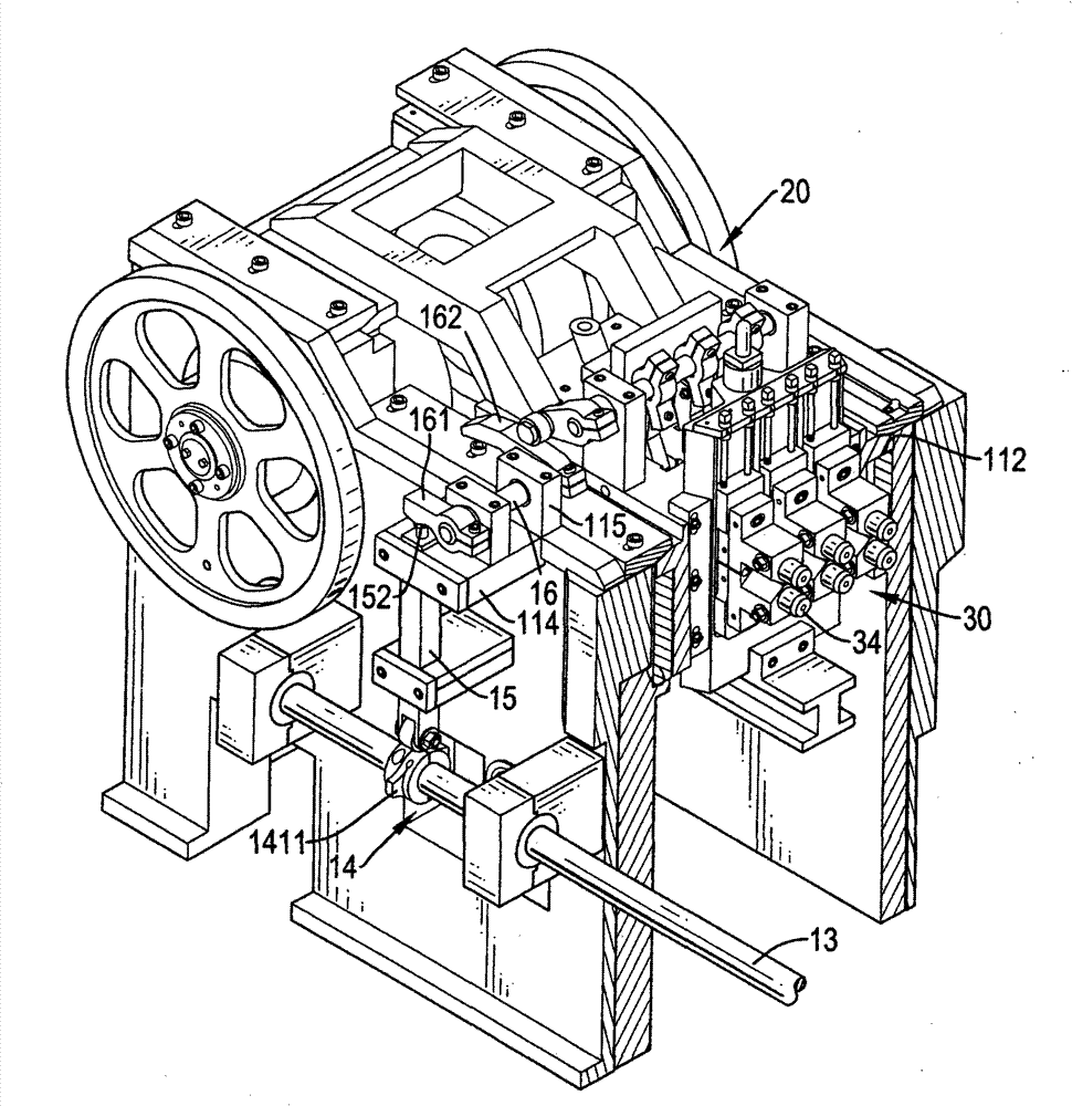
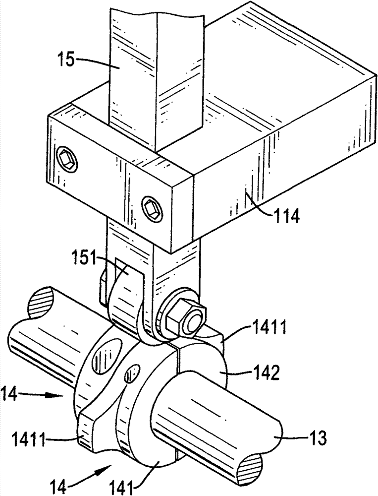
[0076] The present invention is a punching die ejection device of a screw heading machine, please refer to Figure 1 to Figure 7 Preferred embodiments include:

[0077] For a body structure 10, see Figure 1 t...


PUM


Abstract

The invention relates to a punch die ejector for a screw heading machine. An advance and retreat track is formed in the middle of the machine frame; the outer side of the machine frame is provided with an ejector pin and a rotating plate, the ejector pin is alternately abutted against by two cams, and the rotating plate is arranged on the top of the base through the ejector pin in a linkage mode;the advance and retreat track is provided with a propelling seat in a sliding mode; the front surface of the propelling seat is concavely provided with three elongated slots left and right at intervals; an ejection plate is arranged in each elongated slot; the top of the propelling seat is provided with a throw shaft which is linked with the rotating plate; a plurality of linkage arms are combined with the throw shaft; the linkage arms can pull and be matched with the pull arm so as to eject the ejection plate forward; a sliding seat is combined with the front surface of the propelling seat; the front surface of the sliding seat is provided with a plurality of punch dies; and a push pin, which is ejected forward under the linkage action of the ejection plate, is arranged in the front end of each punch die. Thus, in the invention, the push pin can be ejected forward during punch forming, so that the workpiece can be positioned in the die cavity of the master die in deed, thereby achieving good processing quality.

Description

technical field [0001] The invention relates to a device for a screw header, in particular to a punching die ejector for a screw header which can ensure the positioning of materials for processing and can avoid collisions. Background technique [0002] General screw heading machine, such as China Taiwan Patent No. 331193 "Two Die Four Punch Screw Heading Machine" new patent case, the screw heading machine is provided with two main molds which are located in the left and right positions and each has a mold cavity. Iron wires fed sequentially by fixtures are respectively set in each mold cavity, and then the two pairs of upper and lower punches arranged in a matrix form are punched back and forth toward the corresponding mold cavities by means of the advancing and retreating device, so that the iron wire Wire processing into semi-finished products for screws. [0003] The installation form of the aforementioned two pairs of upper and lower dies is as follows: Figure 10 , F...

Claims


Application Information

Patent Timeline
Patent Type & Authority Patents(China)
IPC IPC(8): B21D22/02B21D45/04B21D37/10B21D53/24
Inventor 张智杰
Owner 玟旸机械有限公司
Why Eureka
Try Eureka