
Solar water heater barrier-free hot water discharging system

A technology of solar water heaters and hot water systems, applied in solar thermal power generation, solar thermal devices, heating devices, etc., can solve the problems of wasting water resources, high cost, and inability to empty U-shaped pipes, etc., to ensure normal use, simple Ingenious and unique effect of structural function and technical conception

Inactive Publication Date: 2011-04-06
朱晓俊 +1
View PDF6 Cites 15 Cited by
  • Summary
  • Abstract
  • Description
  • Claims
  • Application Information

AI Technical Summary

Problems solved by technology

The existence of this U-shaped pipe makes it impossible to completely discharge the hot water in the U-shaped pipe even if the solar water heater uses an emptying valve to empty the water stored in the pipe.
The current common practice is to install a manual valve or an electric valve at the lowest point of the user's indoor water pipe to discharge water, but it is a waste of water resources, and it is extremely inconvenient and costly. In addition, if the hot water pipe comes in from the ground, there is no lower point , the water in the U-shaped pipe cannot be drained
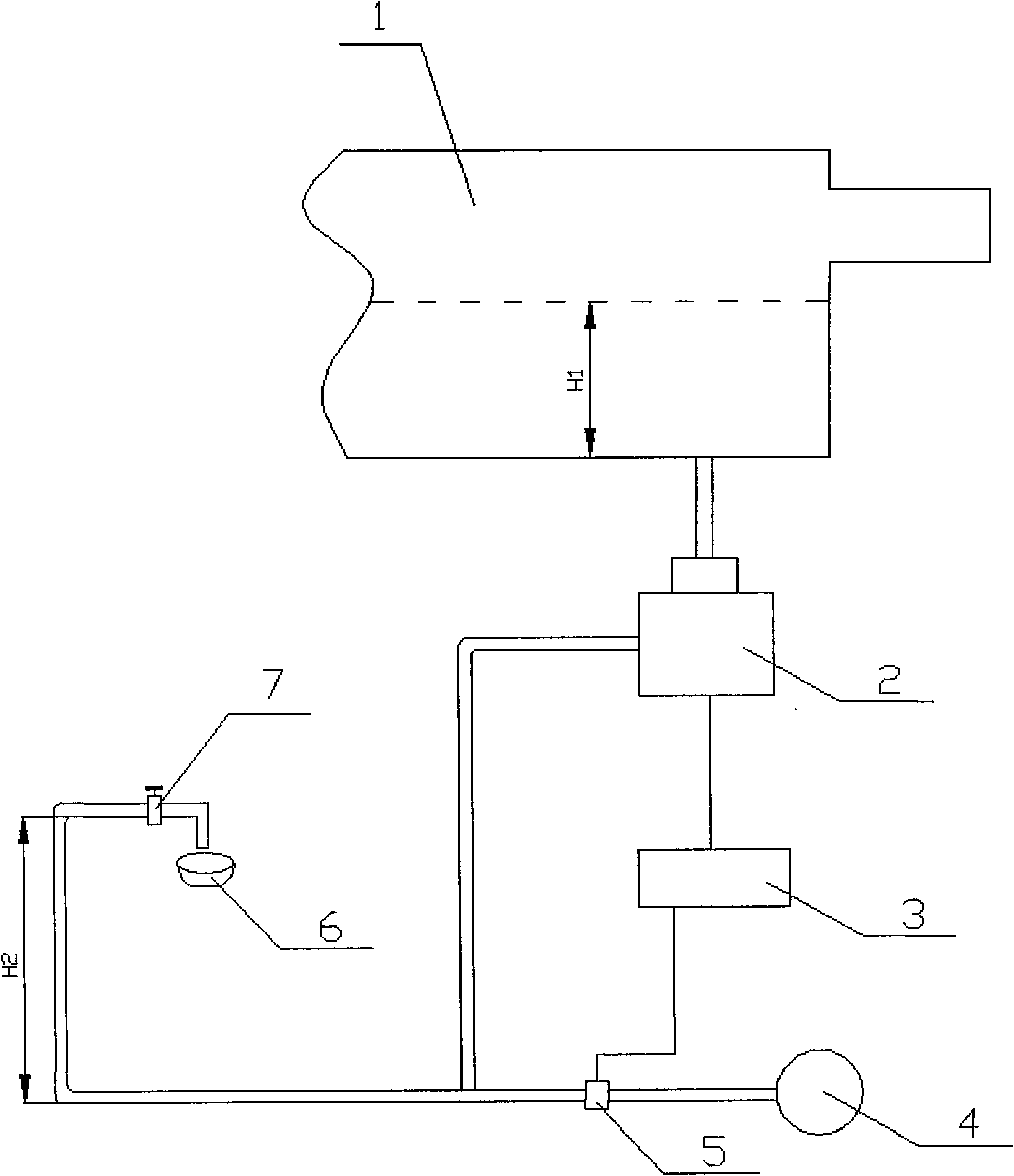
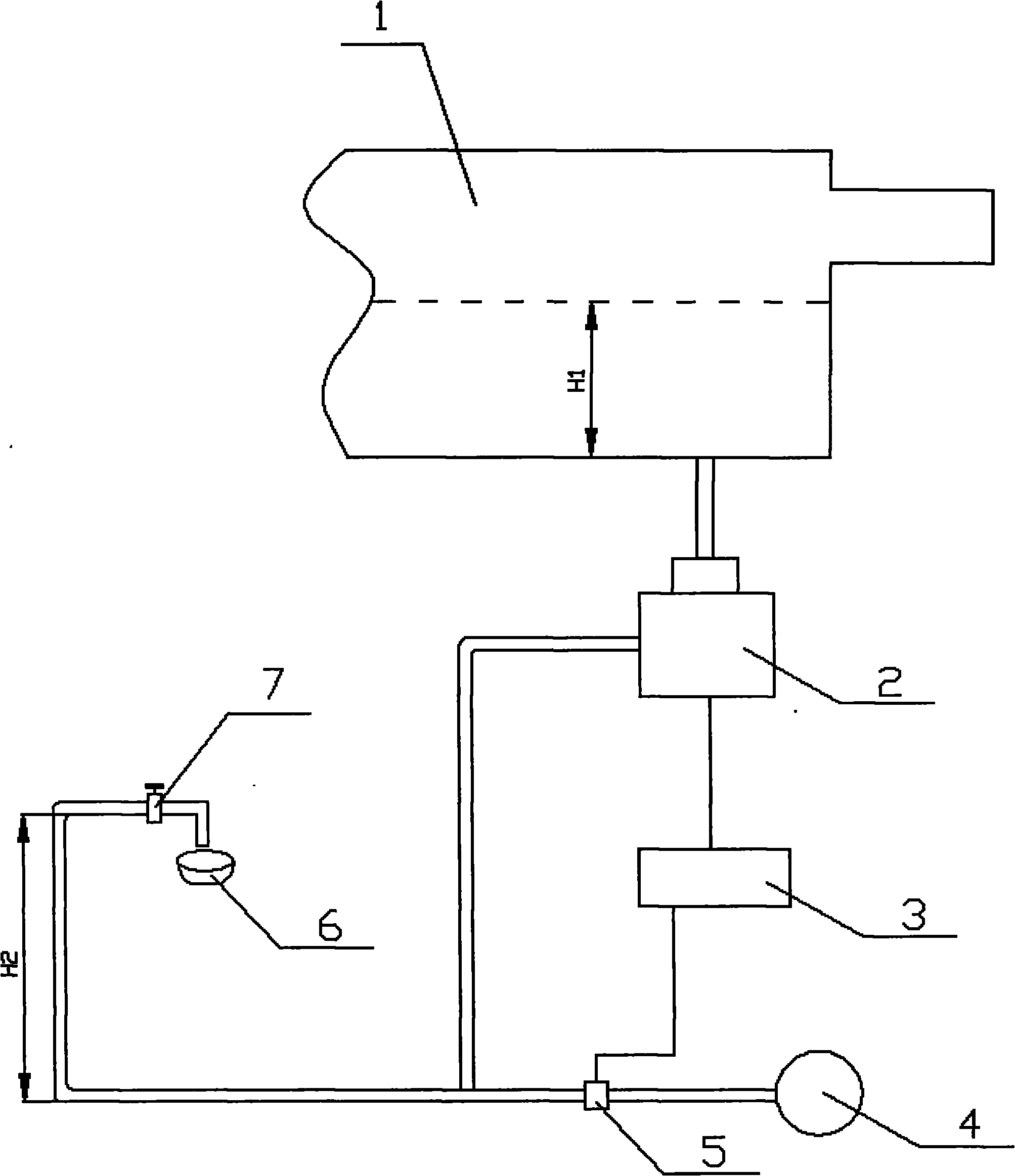
[0006] In this way, when the user uses hot water again, because there is no water in the pipe outside the house but only gas, and the gas is compressible and has a certain degree of elasticity, the water in the solar water heater tank and the water remaining in the pipe inside the house form a U When H1>H2, the hot water can be released, but the pressure is too small; when H1≤H2, the hot water cannot be released, that is to say, the "U" pipe that is often said now cannot use the exhaust valve. This has become a major technical problem that is difficult to solve in the field of solar water heaters.

Method used


Image

  • Solar water heater barrier-free hot water discharging system
  • Solar water heater barrier-free hot water discharging system

Examples


Embodiment Construction

[0014] The specific implementation of the solar water heater barrier-free hot water outlet system of the present invention will be described below with reference to the accompanying drawings.

[0015] Such as figure 1 As shown, the solar water heater barrier-free hot water outlet system of the present invention includes a solar water heater tank 1, the solar water heater tank 1 is connected to a water basin 6 through a pipe and a manual water outlet valve 7 via an emptying valve 2 and is formed as a U-shaped pipe. The U-shaped pipe is connected to the cold water source 4 via the water supply solenoid valve 5, and the drain valve 2 and the water supply solenoid valve 5 are connected to the controller 3 through a control line, and the controller 3 is used to control the drain valve 2 and the water supply solenoid valve 5. Water supply solenoid valve 5, and when the user uses hot water and the height H1 of hot water in the solar water heater tank 1 ≤ the height H2 of the U-shaped...


PUM


Abstract

A solar water heater barrier-free hot water discharging system comprises a solar water heater water tank (1), which is connected with a wash basin (6) through a pipeline via an emptying valve (2) and a manual outlet valve (7) to form a U-shaped pipe. The U-shaped pipe is connected with a cold water source (4) by a water charging solenoid valve (5). The emptying valve and the water charging solenoid valve (5) are connected with a controller (3) through a control line. When a user uses hot water and the height (H1) of the hot water in the solar water heater water tank is less than or equal to the height (H2) of the U-shaped pipe, the controller controls the water charging solenoid valve to open for 1-60s. Due to the improvement on the structural function, the system can effectively smoothly discharge hot water of the solar water heater, thereby ensuring the normal use of the user and solving the technical problem in the field of the solar water heater. In addition, the system is simple in structure and wide in adaptability, and can be conveniently applied to the existing solar water heater.

Description

technical field [0001] The invention relates to a solar water heater, in particular to a barrier-free hot water outlet system of the solar water heater. Background technique [0002] The solar water heater is installed on the roof or the roof, and is connected with the user's water supply pipe through the pipeline. Since there is always water in the pipeline, and the water will not heat up, the user must put a period of cold water before using it. The water will become colder again, and users who are higher from the roof will have more cold water. Poor insulation in northern areas will cause water pipes to freeze. [0003] In order to solve the above problems, technicians have designed an emptying valve to use up the hot water in the pipeline. However, the emptying valve commonly used in solar water heaters can only drain the pipes that do not form a "U" bend. The water in the pipe is completely discharged, but the water in the pipe with a "U" bend cannot be completely rele...

Claims


Application Information

Patent Timeline
IPC IPC(8): F24J2/46F24J2/40
CPCY02E10/40
Inventor 朱晓俊朱开云
Owner 朱晓俊
Learn More