
Impedance test device of low-voltage electric power carrier channel

A low-voltage power carrier and impedance testing technology, applied in measuring devices, measuring resistance/reactance/impedance, measuring electrical variables, etc., can solve the problems that affect the accuracy of the carrier measurement value, cannot measure the impedance phase, and the carrier measurement frequency points are limited.

Active Publication Date: 2011-04-06
HEILONGJIANG ELECTRIC POWER RES INST +1
View PDF4 Cites 18 Cited by
  • Summary
  • Abstract
  • Description
  • Claims
  • Application Information

AI Technical Summary

Problems solved by technology

[0005] The purpose of the present invention is to solve the problem that the frequency characteristics of the high-frequency transformer and the resonant circuit affect the accuracy of the carrier measurement value in the current method of measuring the carrier channel impedance, the carrier measurement frequency points are limited, and only the impedance modulus can be measured, but the impedance phase cannot be measured. , providing a low-voltage power carrier channel impedance test device

Method used


Image

  • Impedance test device of low-voltage electric power carrier channel
  • Impedance test device of low-voltage electric power carrier channel
  • Impedance test device of low-voltage electric power carrier channel

Examples


specific Embodiment approach 1

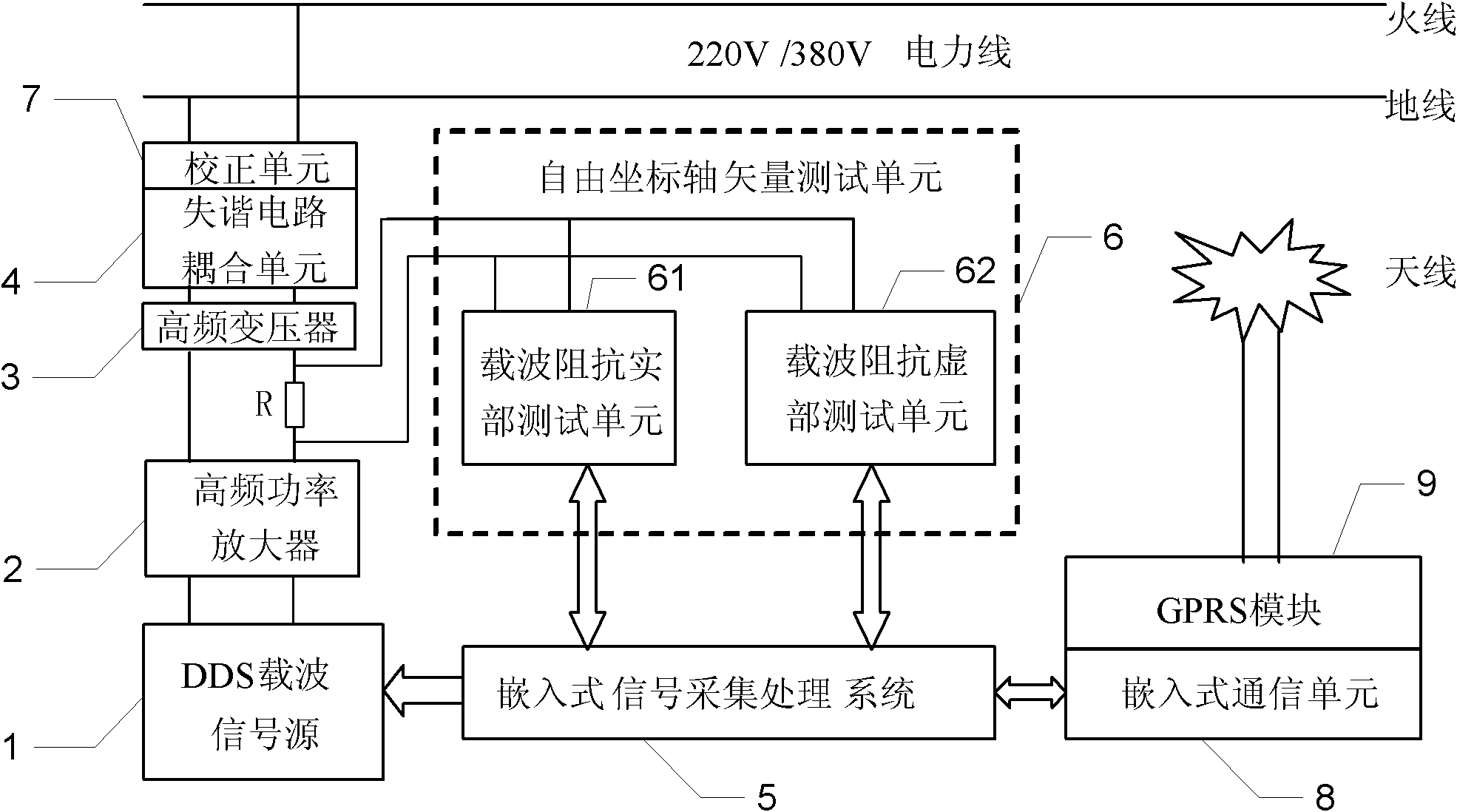
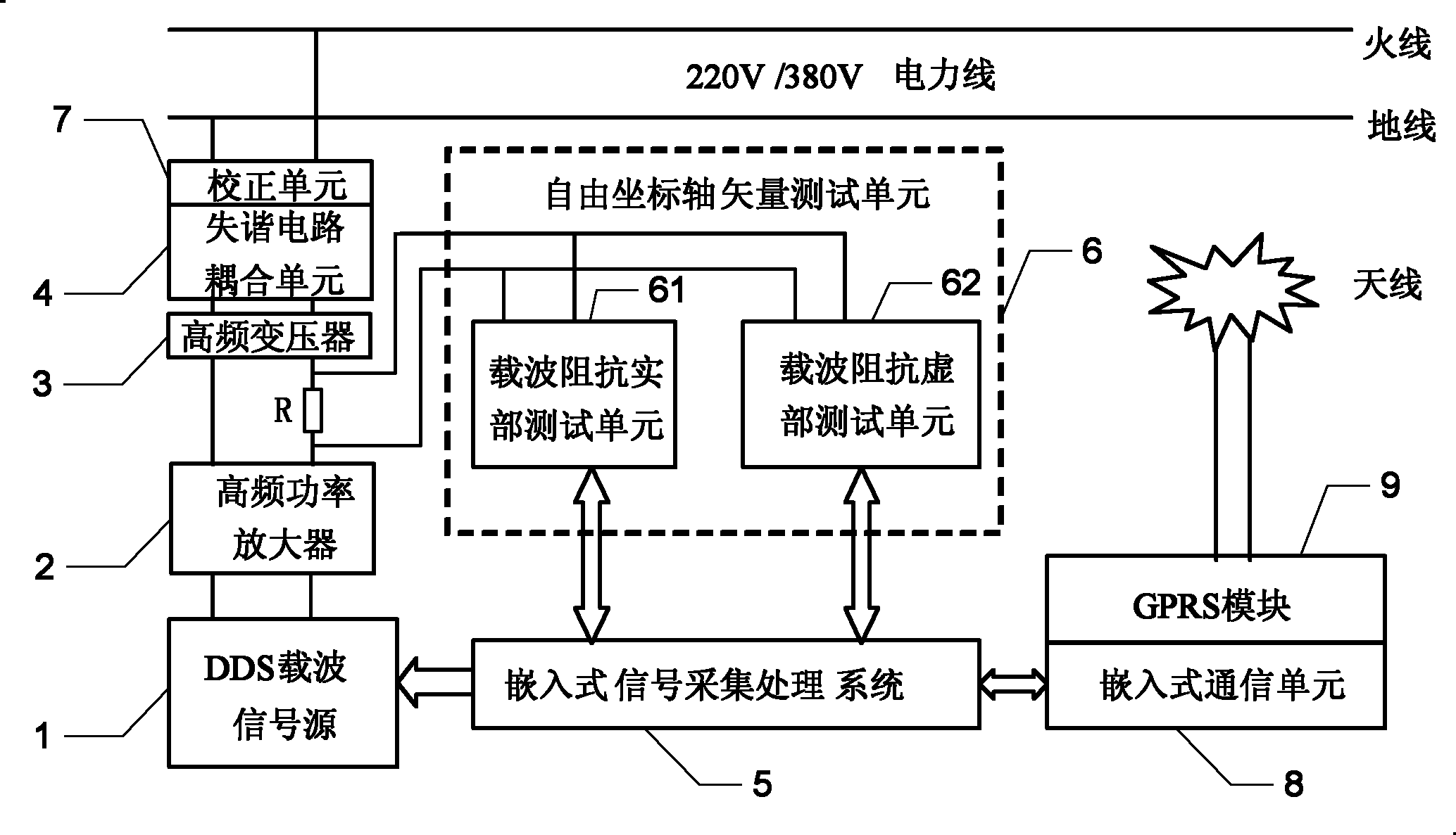
[0013] Specific implementation mode one: the following combination Figure 1 to Figure 2 Describe this embodiment, this embodiment comprises DDS carrier signal source 1, high-frequency power amplifier 2, high-frequency transformer 3, detuning circuit coupling unit 4, embedded signal acquisition and processing system 5 and free coordinate axis vector test unit 6,

[0014] The starting carrier control terminal of the embedded signal acquisition and processing system 5 is connected with the signal control terminal of the DDS carrier signal source 1, and the test input and output terminals of the embedded signal acquisition and processing system 5 are connected with the test input and output terminals of the free coordinate axis vector test unit 6 ,

[0015] The output end of the DDS carrier signal source 1 is connected to the input end of the high frequency power amplifier 2, the output end of the high frequency power amplifier 2 is connected to the primary side of the high frequ...


PUM


Abstract

The invention provides an impedance test device of a low-voltage electric power carrier channel, belonging to the power grid carrier communication field, which solves the problems of the existing method for measuring carrier channel impedance that the frequency characteristics of a high-frequency transformer and a resonant circuit affect the accuracy of the measuring value of a carrier, only the impedance modulus can be measured but the impedance phase can not be measured owing to limited carrier measuring frequency points. In the invention, a starting carrier control terminal of an embedded signal acquisition and processing system is connected with a signal control terminal of a DDS (direct digital synthesis) carrier signal source, testing input-output terminals of the embedded signal acquisition and processing system are connected with testing input-output terminals of a free coordinate axis vector test unit; the DDS carrier signal source, a high-frequency power amplifier and a primary side of a high-frequency transformer are sequentially connected; a load resistor R is connected in series between the high-frequency power amplifier and the primary side of the high-frequency transformer; a secondary side output terminal of the high-frequency transformer is connected with an input terminal of a coupling unit of a detuned circuit; and an output terminal of the coupling unit of the detuned circuit is connected with two tested low-voltage power lines.

Description

technical field [0001] The invention relates to a low-voltage power carrier channel impedance testing device, which belongs to the field of carrier communication of power grids. Background technique [0002] Input impedance is an important parameter to characterize the transmission characteristics of low-voltage power lines. The input impedance of low-voltage power lines is closely related to the frequency of the transmitted power carrier signal. Theoretically, under the ideal condition of no load, the power line is a transmission line with uniform impedance distribution. Under the influence of distributed inductance and distributed capacitance, the input impedance should decrease to a certain value with the increase of frequency; and when the power line When loaded, the input impedance decreases at all frequencies. However, due to the different load types, the impedance changes at different frequencies are also different, so the actual situation is very complicated. Due t...

Claims


Application Information

Patent Timeline
Patent Type & Authority Applications(China)
IPC IPC(8): G01R27/02G01R27/08G08C17/02
Inventor 韩东王学伟陆以彪王琳
Owner HEILONGJIANG ELECTRIC POWER RES INST
Learn More