
Ceramic optical fibre cold coupler

A ceramic and optical fiber technology, applied in the field of ceramic optical fiber cold splices, can solve the problems of inconvenient optical fiber docking, matching oil pollution, loss, etc., to achieve the effect of easy operation, reduce later failures, and improve assembly efficiency

Inactive Publication Date: 2011-04-06
XIANGJIANG TECH
View PDF2 Cites 5 Cited by
  • Summary
  • Abstract
  • Description
  • Claims
  • Application Information

AI Technical Summary

Problems solved by technology

[0003] Aiming at the disadvantages in the prior art that the optical fiber cold connection adopts an unsealed clip-type structure, the matching oil is easily polluted or lost, and the V-shaped groove of the plastic bottom plate is easily deformed by the environment, thus causing inconvenient optical fiber docking. The present invention The purpose is to provide a ceramic optical fiber cold splicer that can conveniently and reliably connect optical fibers

Method used

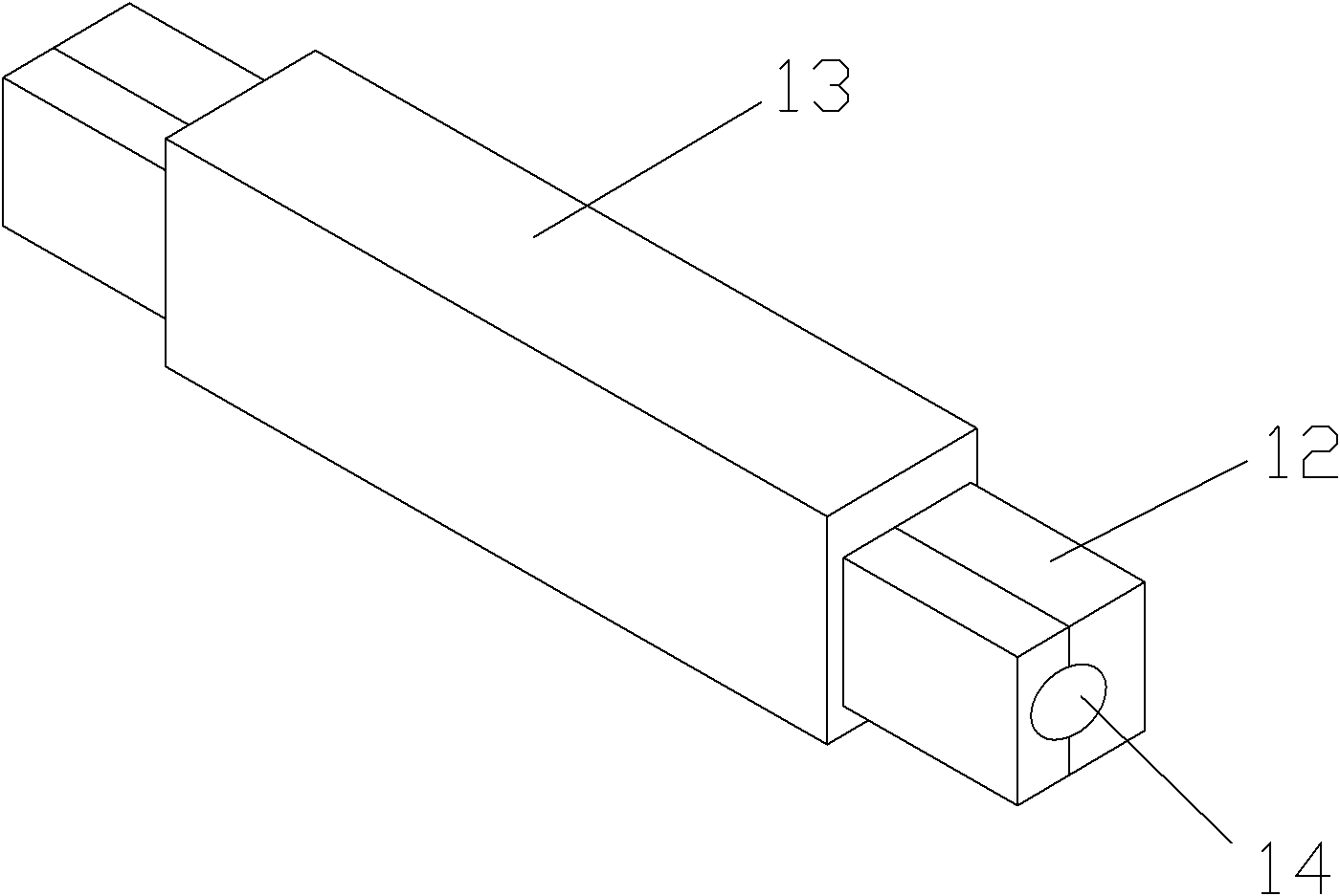
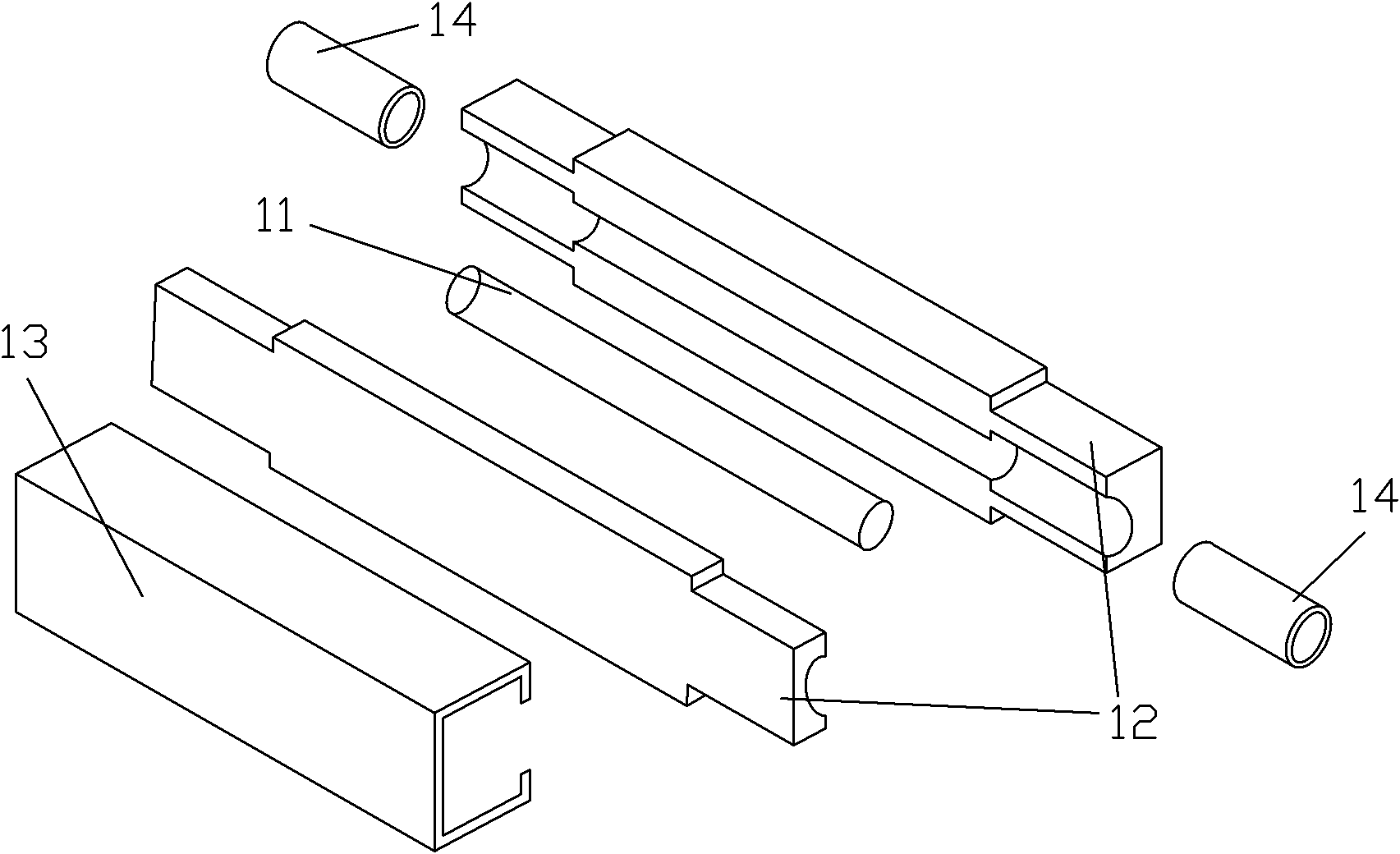

Image

  • Ceramic optical fibre cold coupler
  • Ceramic optical fibre cold coupler
  • Ceramic optical fibre cold coupler

Examples


Embodiment

[0014] see figure 2 and image 3 As shown: the ceramic optical fiber cold joint of the present invention includes a ceramic hollow tube 11, a fixing seat 12 and a stainless steel sleeve 13, the fixing base 12 is connected by a Huff structure, the ceramic hollow tube 11 is located in the fixing base 12, and the stainless steel sleeve 13 is set on the outside of the fixed seat 12, and the shape of the inside of the stainless steel sleeve 12 matches the shape of the fixed seat. The ceramic hollow tube 11 is used to fix the optical fiber. After the optical fiber is processed, the ceramic hollow tube 11 is used to meet the docking of its end face. The optical fiber is wrapped in the ceramic hollow tube 11 to achieve low-loss transmission of optical signals. The material is not affected by any environment, so the optical fiber will not be squeezed due to environmental changes inside the ceramic ferrule, so that the optical fiber can achieve a good connection. Moreover, the cerami...


PUM


Abstract

The invention discloses a ceramic optical fibre cold coupler comprising a ceramic hollow tube, a fixed base and a stainless steel sleeve. The fixed base is connected by using a Hough structure; the ceramic hollow tube is arranged in the fixed base; the stainless steel sleeve is sleeved on the outer side of the fixed base; and the shape of the inner side of the stainless steel sleeve is matched with that of the fixed base. As the optical fibre is fixed by using the ceramic hollow tube and the cavity in the ceramic hollow tube is sealed, the adoption of the ceramic optical fibre cold coupler cannot cause deformation inside the ceramic hollow tube under the external environment, and pollution and loss of matching oil in the cavity, and the ceramic optical fibre cold coupler is convenient for field operators to operate, can improve the assembling efficiency and the coupling reliability of the optical fibres, is suitable for various severe environments and beneficial to the reduction of later faults, and has remarkable practical value.

Description

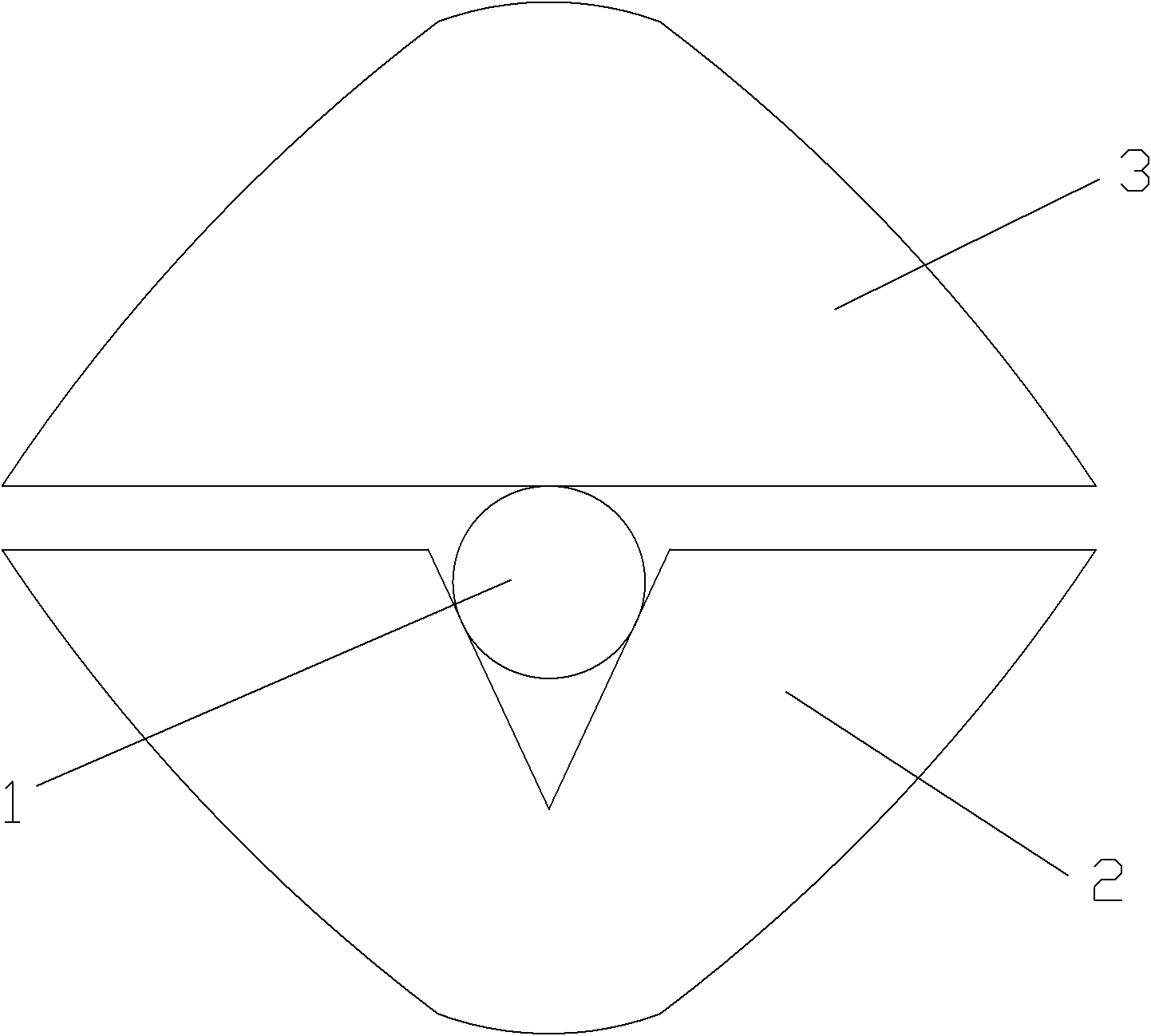
technical field [0001] The invention relates to an optical fiber connection technology for an optical fiber termination point, and more specifically relates to a ceramic optical fiber cold splicer. Background technique [0002] End-to-end splicing is the process of making an active connection at the end of the fiber. The active connection of optical fibers is generally completed through optical fiber active connectors, but the production process of traditional active connectors is very complicated, and requires skilled technicians to operate, and the production cycle is also long, so it is used at the end of the optical fiber at the construction site of the integrated wiring This fiber optic connector is not possible. For this reason, most of the optical fiber cold splicing technology is used now. The existing cold splice structure of optical fiber is as follows: figure 1 As shown, it mainly adopts a clip-type structure. Before splicing, use a cleaver to smooth the end fac...

Claims


Application Information

Patent Timeline
Patent Type & Authority Applications(China)
IPC IPC(8): G02B6/38G02B6/36
Inventor 沙正勇
Owner XIANGJIANG TECH
Learn More