
Motor stator piece punching blanking stamping technology and key die thereof

A technology of punching and blanking, stator and rotor, which is applied in the manufacture of stator/rotor body, etc., to achieve obvious effects, avoid waviness, and reduce stamping steps

Active Publication Date: 2011-04-06
LANZHOU ELECTRIC CORP
View PDF4 Cites 3 Cited by
  • Summary
  • Abstract
  • Description
  • Claims
  • Application Information

AI Technical Summary

Problems solved by technology

When the rotor groove is a closed groove, using the existing technology, stamping out the rotor groove shape in step ④ will cause large waves on the rotor blades, which are very obvious on the iron core after lamination and cannot be eliminated, affecting the performance of the motor

Method used


Image

  • Motor stator piece punching blanking stamping technology and key die thereof
  • Motor stator piece punching blanking stamping technology and key die thereof
  • Motor stator piece punching blanking stamping technology and key die thereof

Examples


Embodiment Construction

[0028] In an embodiment of the punching and blanking stamping process of motor stator and rotor sheet and its key mold provided by the present invention, the stamping process includes the following steps:

[0029] ① Re-punching the outer circle of the stator and the rotor shaft hole: on the punching machine, punch the outer circle of the stator, the slot of the stator buckle and the outer marking groove of the stator, and at the same time punch the shaft hole of the rotor and the keyway of the rotor to obtain the blank of the stator and rotor;

[0030] ②Single punch stator slot: On the single slot machine, position the stator and rotor blank with the rotor shaft hole and the rotor keyway, single punch the stator slot, and get the stator and rotor blank with the stator slot punched;

[0031] ③Single punching of rotor slots and separation of stator and rotor slices: On the single slot machine, the stator and rotor blanks punched with stator slots are positioned with the rotor sha...


PUM


Abstract

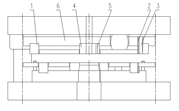
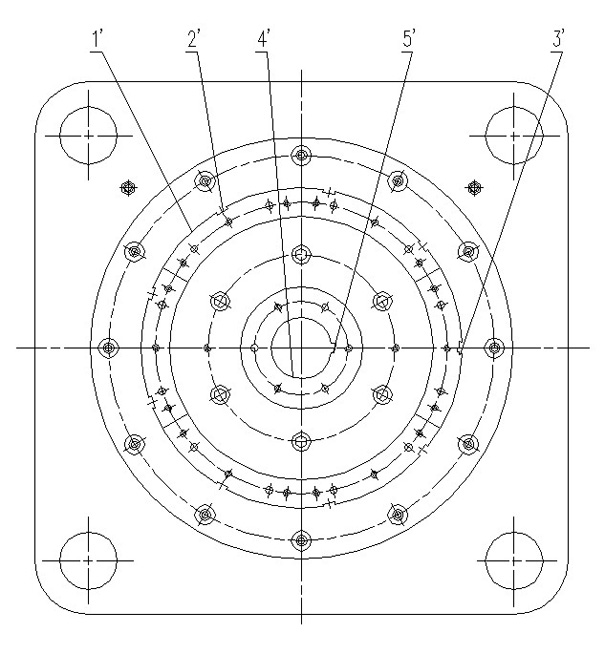
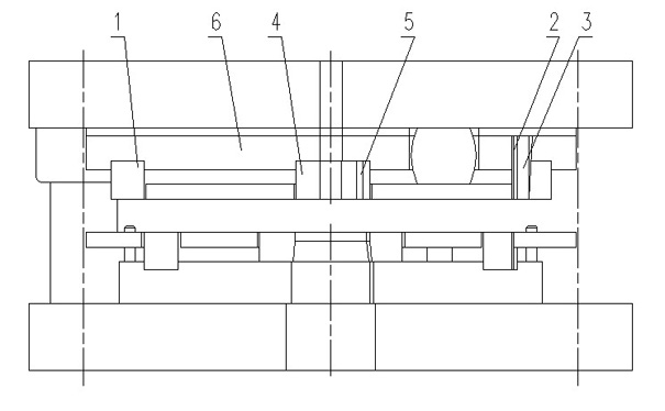
The invention provides a motor stator piece punching blanking stamping technology and a key die thereof. The stamping technology comprises the following steps: 1) punching a stator excircle and a rotor shaft hole again; 2) singly punching a stator slot; 3) singly punching a rotor slot, and simultaneously separating the rotor piece. The key die is composed of a top die part, a lower die part and aguiding part, wherein the top die part comprises an upper cutting edge provided with a stator excircle die, a cramp slot punch, an external marking slot punch, a rotor shaft hole terrace die and the upper cutting edge of a keyway punch; the upper cutting edge is fixedly arranged on an upper fixed plate, and the setting position and the size of the upper cutting edge correspond to the position andthe size of the stator excircle required to be stamped, the cramp slot, the external marking slot, the rotor shaft hole and the keyway; and the lower die part comprises a low cutting edge corresponding to the upper cutting edge. When the invention stamps, one working procedure is omitted so as to reduce blank transportation one time, lower labor intensity and improve stamping efficiency; during mass production, effect is especially obvious. The phenomenon that the stator piece slot has irregular shape and the rotor piece has waviness rate can be avoided, and stamping effect is excellent.

Description

technical field [0001] The invention relates to the field of motor manufacturing, in particular to a stamping process for punching and blanking motor stator and rotor slices and a key mold thereof. Background technique [0002] The stator and rotor are the core components of the motor. They are formed by stamping the entire sheet with a mold, and then stacking the stator and rotor pieces separately. A method with relatively high efficiency is to use four-sequence four-pair molds and corresponding auxiliary special tools to complete the stamping of stator and rotor segments. The stamping steps are: [0003] ①Blanking of stator and rotor blanks: stamping the rotor shaft hole and the outer circle of the stator; [0004] ② Repunching the stator buckle groove, marking groove and rotor shaft hole keyway; [0005] ③Single punch stator slot and separation to obtain stator slices; [0006] ④ Rotor slices are obtained by single punching the rotor slots. [0007] In steps ① and ②,...

Claims


Application Information

Patent Timeline
Patent Type & Authority Applications(China)
IPC IPC(8): H02K15/02
Inventor 王健马永和张晓红宋旺军安召军
Owner LANZHOU ELECTRIC CORP
Learn More