
All-vanadium flow battery

An all-vanadium redox flow battery and liquid flow technology, applied in battery electrodes, regenerative fuel cells, circuits, etc., can solve the problems of increasing the thickness of the conductive plate, increasing the internal resistance, and increasing the thickness.

Inactive Publication Date: 2015-01-07
山西金能世纪科技有限公司
View PDF12 Cites 0 Cited by
  • Summary
  • Abstract
  • Description
  • Claims
  • Application Information

AI Technical Summary

Problems solved by technology

Although the flow resistance of the vanadium electrolyte has been reduced, since most of the vanadium electrolyte flows directly above the electrode surface, only a small part flows through the inside of the electrode. The mass transfer of the vanadium electrolyte inside the electrode is slow and the diffusion polarization is large. Moreover, the structure of the stack is complicated, the sealing is difficult, the thickness increases, and the internal resistance increases, resulting in low power density, vanadium utilization and energy efficiency of the stack.
[0018] Chinese patent 201110200880.3 proposes to open a vanadium electrolyte flow channel on the conductive plate. Although the flow resistance of the vanadium electrolyte is reduced, because most of the vanadium electrolyte flows directly through the flow channel of the conductive plate, only a small part passes through the inside of the electrode. Flow, the mass transfer of vanadium electrolyte in the electrode is slow, the diffusion polarization is large, and because there are flow channels on both sides of the conductive plate, the thickness of the conductive plate increases, the processing is difficult, the cost increases, and the internal resistance increases, resulting in the power density of the stack. , low vanadium utilization and energy efficiency
[0019] Chinese patent 200910078434.2 proposes to open a vanadium electrolyte flow channel on the electrode, which partially solves the problems of slow mass transfer and large diffusion polarization of the vanadium electrolyte inside the electrode, but still a considerable part of the vanadium electrolyte flows directly from the flow channel on the electrode. However, only a small part flows through the inside of the electrode. The mass transfer of the vanadium electrolyte in the electrode is slow, the diffusion polarization is large, and the electrode processing is complicated. There are flow channel grooves on the electrode, which increases the internal resistance of the stack. Resulting in lower power density, vanadium utilization and energy efficiency of the stack
[0020] It can be seen from the above that as long as the aspect ratio of the electrode is still between 1 and 1.5, and the shape of the monolithic battery is still close to a square, no matter whether the vanadium electrolyte guide net is set on the electrode surface or the vanadium electrolyte is placed on the conductive plate Neither the electrolyte channel nor the vanadium electrolyte channel on the electrode can completely solve the problems of difficult mass transfer and large diffusion polarization of the vanadium electrolyte in the high-power stack, and it also increases the internal capacity of the stack. resistance and stack cost
In order to completely solve the world-wide problems of difficult mass transfer and large diffusion polarization of vanadium electrolyte in the electrode, and further improve the power density, vanadium utilization rate and energy efficiency of high-power stacks, it is necessary to overcome traditional technical prejudices. In-depth study of the effect of aspect ratio on the flow of vanadium electrolyte through the electrodes, the power density of the stack, vanadium utilization and energy efficiency

Method used


Image

  • All-vanadium flow battery
  • All-vanadium flow battery
  • All-vanadium flow battery

Examples


Embodiment Construction

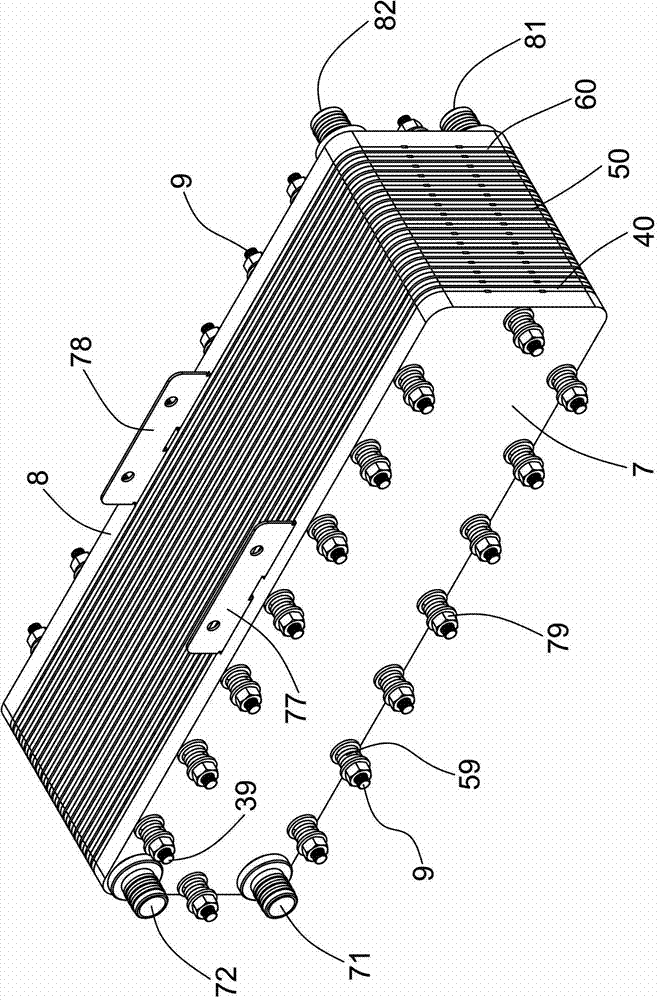
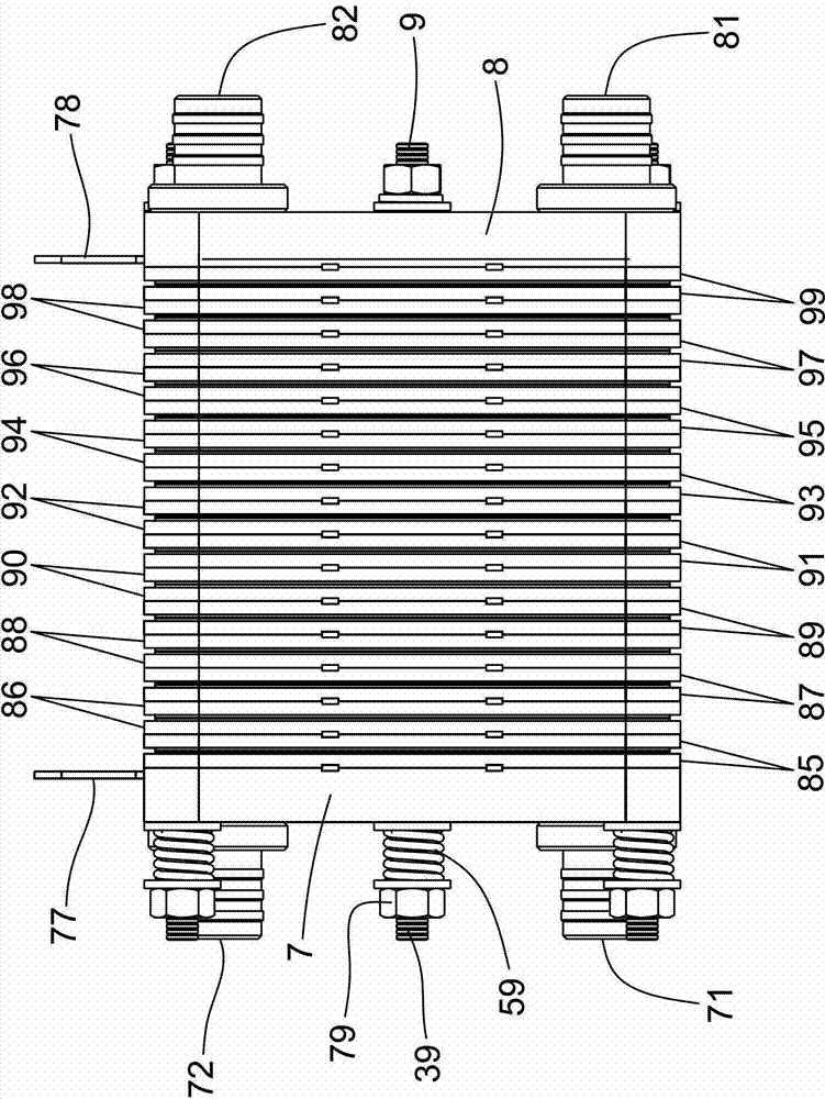
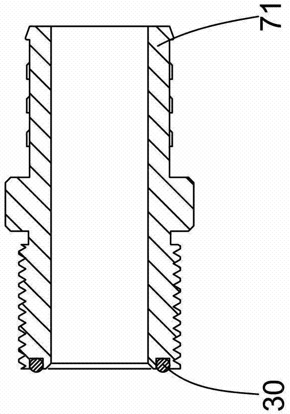
[0095] Labels in the figure:

[0096] 1 Positive flow frame plate 2 Negative flow frame plate 3 Conductive plate

[0097] 4 positive electrode 5 ion exchange membrane 6 negative electrode

[0098] 7 Positive end pressure plate 8 Negative end pressure plate 9 Fasteners

[0099] 10 inner frame 11 liquid inlet hole 12 liquid outlet hole

[0100] 13 Liquid outlet hole 14 Liquid outlet hole 15 Locking pin

[0101] 16 Locking hole 17 Cover plate 18 Cover plate

[0102] 19 Annular concave table 20 Inner frame 21 Liquid inlet hole

[0103] 22 Liquid hole 23 Liquid hole 24 Liquid outlet

[0104] 25 locking pin 26 locking hole 27 cover plate

[0105] 28 cover plate 29 annular concave platform 30 sealing ring

[0106] 31 branch flow channel 32 narrow comb groove 33 long straight groove

[0107] 34 narrow comb slot 35 positioning pin 36 positioning hole

[0108] 37 long straight slot 38 wide comb slot 39 screw rod

[0109] 40 Positive electrode assembly 41 Branch channel 42 Narr...


PUM

PropertyMeasurementUnit
heightaaaaaaaaaa
widthaaaaaaaaaa
heightaaaaaaaaaa

Abstract

The invention discloses an all-vanadium flow battery. Flow frame plates are provided with liquid inlet holes and liquid outlet holes; the front faces of the flow frame plates are provided with liquid inlet branch flow channels and liquid outlet branch flow channels; the flow frame plates are arranged in sequence sequentially and alternatively in a front face to front face and back face to back face way; an ion exchange membrane is clamped between the front faces of adjacent flow frame plates; a current-conducting plate is clamped between opposite back faces of adjacent flow frame plates; electrodes are arranged in inner frames of the flow frame plates; the aspect ratios of the electrodes are 3-15; the heights of the electrodes are 1-25 centimeters; and the widths of the electrodes are less than or equal to 200 centimeters. In the all-vanadium flow battery, electrodes of large aspect ratios, small heights and large widths are adopted. The all-vanadium flow battery has the advantages of simple structure, small quantity of assemblies, small thickness, small size, low internal resistance, easiness in processing, convenience in assembling, good mass transfer effect and low diffusion polarization of vanadium electrolytes inside the electrodes, low self-discharge current, high power density, high vanadium utilization ratio, high energy efficiency, low cost and high benefit.

Description

technical field [0001] The invention belongs to the field of flow batteries, and in particular relates to an all-vanadium flow battery. Background technique [0002] Today, when the world economy is struggling to recover, traditional energy sources are increasingly scarce, and the earth's environment is deteriorating, a wave of new energy industry revolution that has an extremely profound and far-reaching impact on human society is sweeping the world! The inherent randomness, volatility, intermittency, difficulty in peak shaving, and difficulty in grid connection of new energy determine that its large-scale development must be supported by advanced energy storage technology. [0003] The all-vanadium redox flow battery conducts electrochemical reactions through the circulation of vanadium electrolytes in different valence states through the electrodes from bottom to top, so as to realize the mutual conversion of chemical energy and electrical energy. All-vanadium redox flow...

Claims


Application Information

Patent Timeline
Patent Type & Authority Patents(China)
IPC IPC(8): H01M8/18H01M4/86
CPCY02E60/528Y02E60/50
Inventor 郑重德陈利华王东明刘杰鲁春芳任金华
Owner 山西金能世纪科技有限公司
Learn More