Electronic ballast with novel auxiliary winding parallel firing circuit structure

An electronic ballast and auxiliary winding technology, applied in the field of electronic ballasts, can solve the problems of low efficiency of a voltage-doubling series ignition circuit, improve the success rate of one-time ignition, ensure the success rate of one-time ignition, and increase the breakdown voltage effect of value

Inactive Publication Date: 2011-04-06
ZHEJIANG UNIV OF TECH
View PDF3 Cites 0 Cited by
  • Summary
  • Abstract
  • Description
  • Claims
  • Application Information

AI Technical Summary

Problems solved by technology

[0007] The present invention solves the problem of low efficiency of the voltage doubling series ignition circuit of the existing electronic ballast, and provides an electronic ballast with high efficiency and simple structure with a new auxiliary winding parallel ignition circuit structure

Method used


Image

  • Electronic ballast with novel auxiliary winding parallel firing circuit structure
  • Electronic ballast with novel auxiliary winding parallel firing circuit structure
  • Electronic ballast with novel auxiliary winding parallel firing circuit structure

Examples


Embodiment Construction

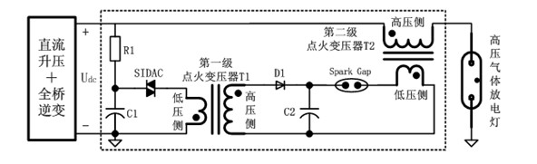
[0028] refer to Image 6 , an electronic ballast with a new type of auxiliary winding parallel ignition circuit structure, including an input filter 2 connected in cascade in order to cut off the high-frequency interference between the battery 1 and the device, and used to convert the input to the battery 1 A DC-DC flyback converter 4 with a high-grade DC voltage boost, a DC-AC full-bridge inverter circuit 6 for converting high-voltage direct current into a high-voltage square wave voltage, the front end of the input filter 2 is connected to a battery 1 , the DC-AC full-bridge inverter circuit 6 is connected in parallel with a continuous arc circuit 5 and an auxiliary winding that temporarily provides energy for the high-pressure gas discharge lamp 31 when the two electrodes of the high-pressure gas discharge lamp 31 are broken down Ignition circuit 3; the auxiliary winding parallel ignition circuit 3 includes an auxiliary winding voltage doubling circuit, a boost circuit, a h...


PUM


Abstract

The invention discloses an electronic ballast with a novel auxiliary winding parallel firing circuit structure. The electronic ballast comprises an input filter, a direct current-direct current (DC-DC) flyback converter and a direct current-alternating current (DC-AC) full-bridge inverter circuit cascaded in turn, wherein the front end of the input filter is connected with a storage battery, and the DC-AC full-bridge inverter circuit is connected in parallel with a continuous arc circuit and an auxiliary winding parallel firing circuit; the auxiliary winding parallel firing circuit comprises an auxiliary winding voltage doubling circuit, a boosted circuit, a blocking high-voltage diode and a relay; the output end of the auxiliary winding voltage doubling circuit is connected with the continuous arc circuit and the boosted circuit; the boosted circuit is connected in parallel with the blocking high-voltage diode and a high-pressure gas discharge lamp; and the high-pressure gas discharge lamp is connected in parallel with the relay. The electronic ballast has the advantages of promoting the breakdown voltage value, ensuring the success rate of one-time ignition, reducing the volume of a high-pressure firing coil and effectively improving the efficiency and work reliability of the whole electronic ballast machine.

Description

technical field [0001] The invention relates to an electronic ballast with a novel auxiliary winding parallel ignition circuit structure for high-pressure gas discharge lamps. Background technique [0002] Electronic ballasts for high-pressure gas discharge lamps include a high-voltage ignition circuit and a steady-state power supply circuit. The ignition circuit and steady-state power supply circuit can generally be connected in series or in parallel. The steady-state power supply circuit includes a DC boost circuit and a full-bridge inverter circuit. The high-voltage generating circuit of the ignition circuit generally has a single-stage boost circuit and a double-stage boost circuit. [0003] A single-stage boost circuit connected in series, such as figure 1 As shown, this circuit generally requires a high turn ratio. Because the high-voltage coil flows the lamp current, the wire used should not be too thin, which will make the volume of the high-voltage transformer lar...

Claims


Application Information

Patent Timeline
Patent Type & Authority Applications(China)
IPC IPC(8): H05B41/288
CPCY02B20/204Y02B20/00
Inventor 戚军张晓峰
Owner ZHEJIANG UNIV OF TECH
Why Eureka
Try Eureka