
Throwing type fracturing equipment

A drop-in, fracturing technology, which is applied to weapons accessories, mining fluids, fuzes, etc., can solve problems such as cable knotting, cable damage, and failure to construct, so as to save manpower and material resources, avoid knotting when encountering obstacles, and improve success. rate effect

Inactive Publication Date: 2007-08-15
中国兵器工业第二一三研究所
View PDF3 Cites 0 Cited by
  • Summary
  • Abstract
  • Description
  • Claims
  • Application Information

AI Technical Summary

Problems solved by technology

The main defects of the cable conveying fracturing process are: (1) each construction operation needs to be equipped with equipment such as cable cars and magnetic locators, and the construction site must also control electricity and high-frequency communication equipment; (2) During the process, the cable will be knotted when encountering resistance, resulting in shutdown or rework; (3) the elongation of the cable is uncertain with time and temperature changes, which makes the action position of the electric igniter deviate from the target layer; (4) the process is affected by Time and climatic conditions are greatly restricted, and construction cannot be carried out at night and under severe climatic conditions such as strong wind, sand, rain and snow; (5) During the fracturing operation, high-temperature and high-pressure gas will cause damage to the cable, which will cost a lot human and material resources
The main defects of this fracturing technique are as follows: (1) oil pipes must be put into the well one by one each time the fracturing operation is carried out, and then taken out from the well one by one at the end, not only the process is complicated, but the operation cycle It lasts for several days, and this process is not suitable for low-yield wells and old oil wells that already have tubing downhole; (2) During the process of going down the well, the pressure-activated igniter needs to add water to it section by section from the wellhead. The impact of water on the igniter may change the ignition value of the igniter, resulting in the accident that the igniter ignites before reaching the target reservoir; (3) During construction operations, the speed of lifting and lowering the tubing or falling objects will affect the construction quality and construction quality. safety in the process

Method used


Image

  • Throwing type fracturing equipment
  • Throwing type fracturing equipment

Examples


Embodiment Construction

[0021] The present invention will be further described in detail below in conjunction with the accompanying drawings and preferred embodiments.

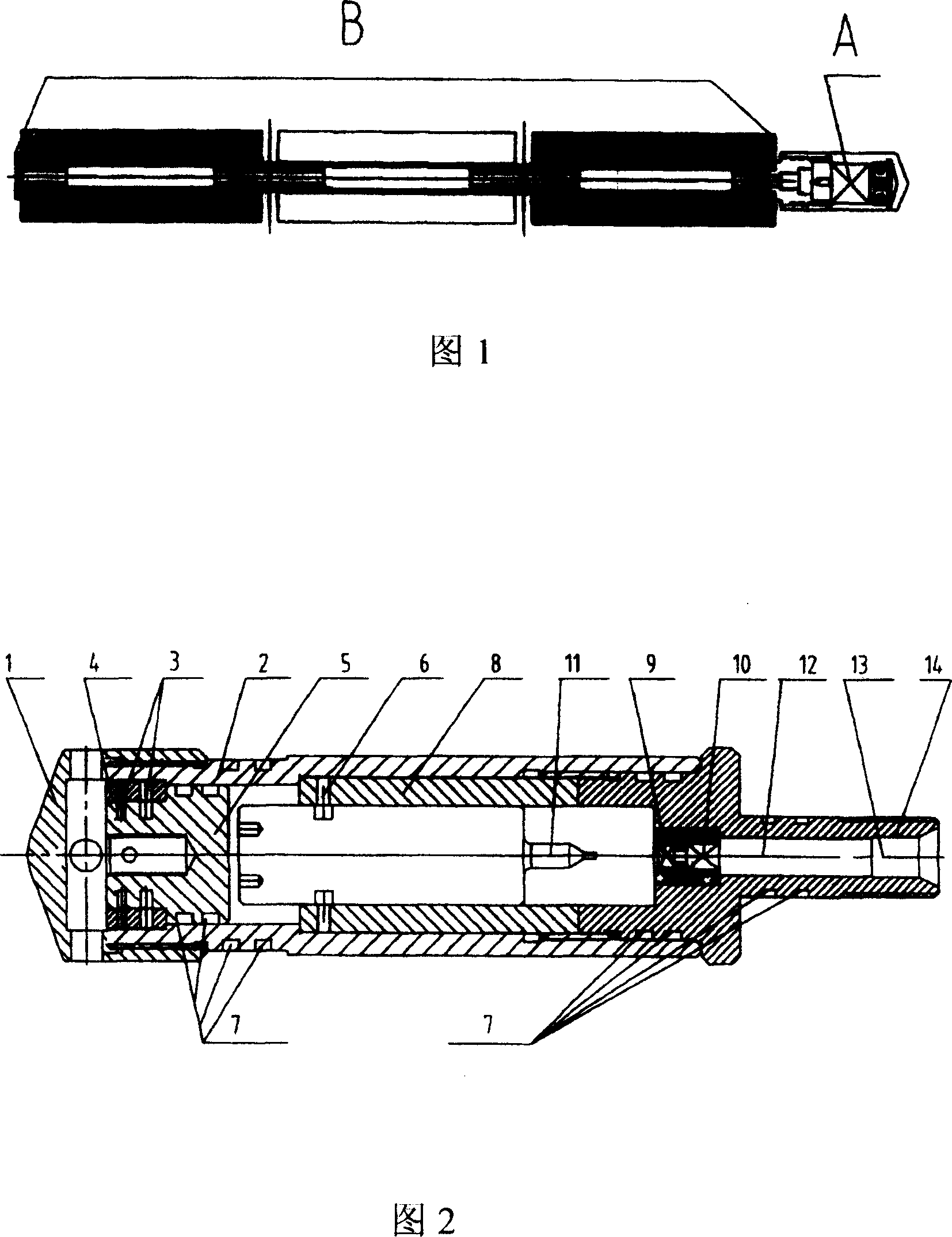
[0022] As shown in Figure 1, the first preferred embodiment of the present invention consists of a pressure igniter A and a high-energy gas generator B. The pressure igniter A is connected with the high-energy gas generator B through the connecting body of its firing mechanism.

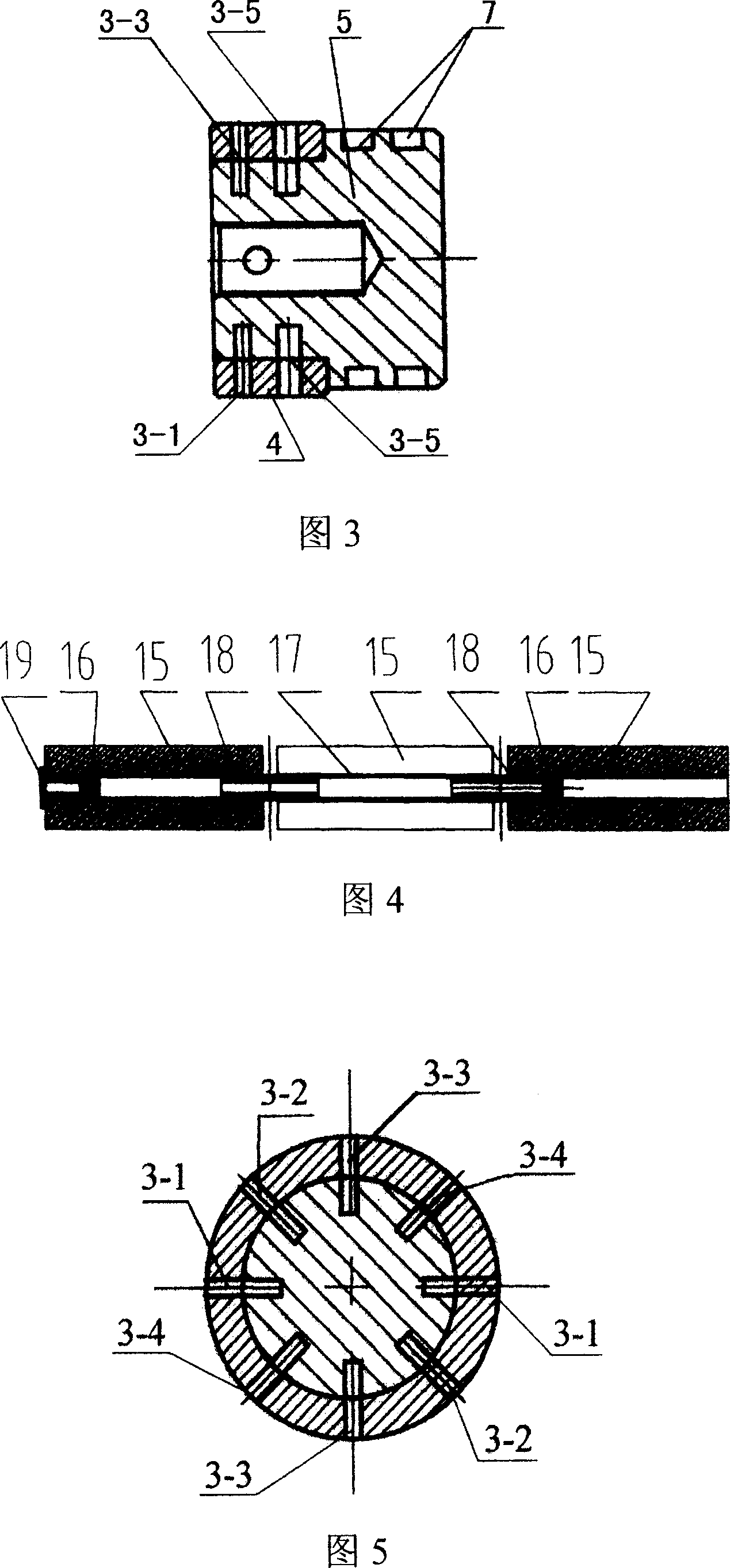
[0023] Referring to Fig. 2, the pressure igniter A of this preferred embodiment includes a tail cap 1, a body 2, a pressure release mechanism, a firing pin assembly, and an ignition mechanism. The body 2 is a cylindrical shell made of steel with multiple central stepped through holes, one end of which is provided with an external thread and the other end is provided with an internal thread. The tail cover 1 has internal threads and radial through holes. The pressure release mechanism includes a pressure bearing pin 3, a pressure bearing ring 4 and a piston...


PUM


Abstract

The invention discloses a throwing compression fracture machine that is suited to oil or gas throwing compression fracture effect increasing technology. It is made up of piezo ignition machine and high energy gas generator. The feature is that the piezo ignition machine could cut off the pressure bearing bolt by function of the liquid column, and make the plunger move to drive the firing pin to knock percussion cap. The percussion cap would fire the starting cartridge, powder and powder column. The fire output by the piezo ignition machine would fire the plural powder columns in high energy gas generator and compressing the object storing layers to fracture. The invention is easy to operate and sharply decreases the consumption of manpower and material.

Description

technical field [0001] The invention belongs to the technical field of oil and gas well high-energy gas production and efficiency enhancement operations, and in particular relates to a drop-in fracturing device suitable for the oil and gas well fracturing efficiency enhancement process. Background technique [0002] During the continuous exploitation of old oil wells, there will be precipitation of petroleum coal tar colloids and asphaltene, precipitation of paraffin and salt, emulsion, clay and fresh water reaction expansion in the oil rock formation; in addition, in the process of drilling and oil testing, oil The rock formation will also be polluted by mud; various impurities will also invade into the oil rock formation during workover. The combination of the above conditions leads to the deterioration of the permeability near the wellbore and the decrease of oil productivity. Therefore, different fracturing stimulation measures can be adopted according to the downhole g...

Claims


Application Information

Patent Timeline
Patent Type & Authority Patents(China)
IPC IPC(8): E21B43/263F42C15/33E21B43/26
Inventor 王秀芝惠宁利王锋张锋
Owner 中国兵器工业第二一三研究所
Learn More