Integrated igniter control circuit

A control circuit and igniter technology, applied in automatic control, automatic control, electrical automatic control, etc., can solve the problems of small ignition energy and high energy consumption, and achieve the effect of large ignition energy and fuel consumption saving.

Inactive Publication Date: 2014-10-22
CHONGQING HUARI ELECTRICAL GOODS DEV
View PDF4 Cites 0 Cited by
  • Summary
  • Abstract
  • Description
  • Claims
  • Application Information

AI Technical Summary

Problems solved by technology

[0002] The current igniter adopts analog or digital ignition control and high-voltage separation working method. The traditional method consumes more energy and has less ignition energy.

Method used


Image

  • Integrated igniter control circuit

Examples


Embodiment Construction

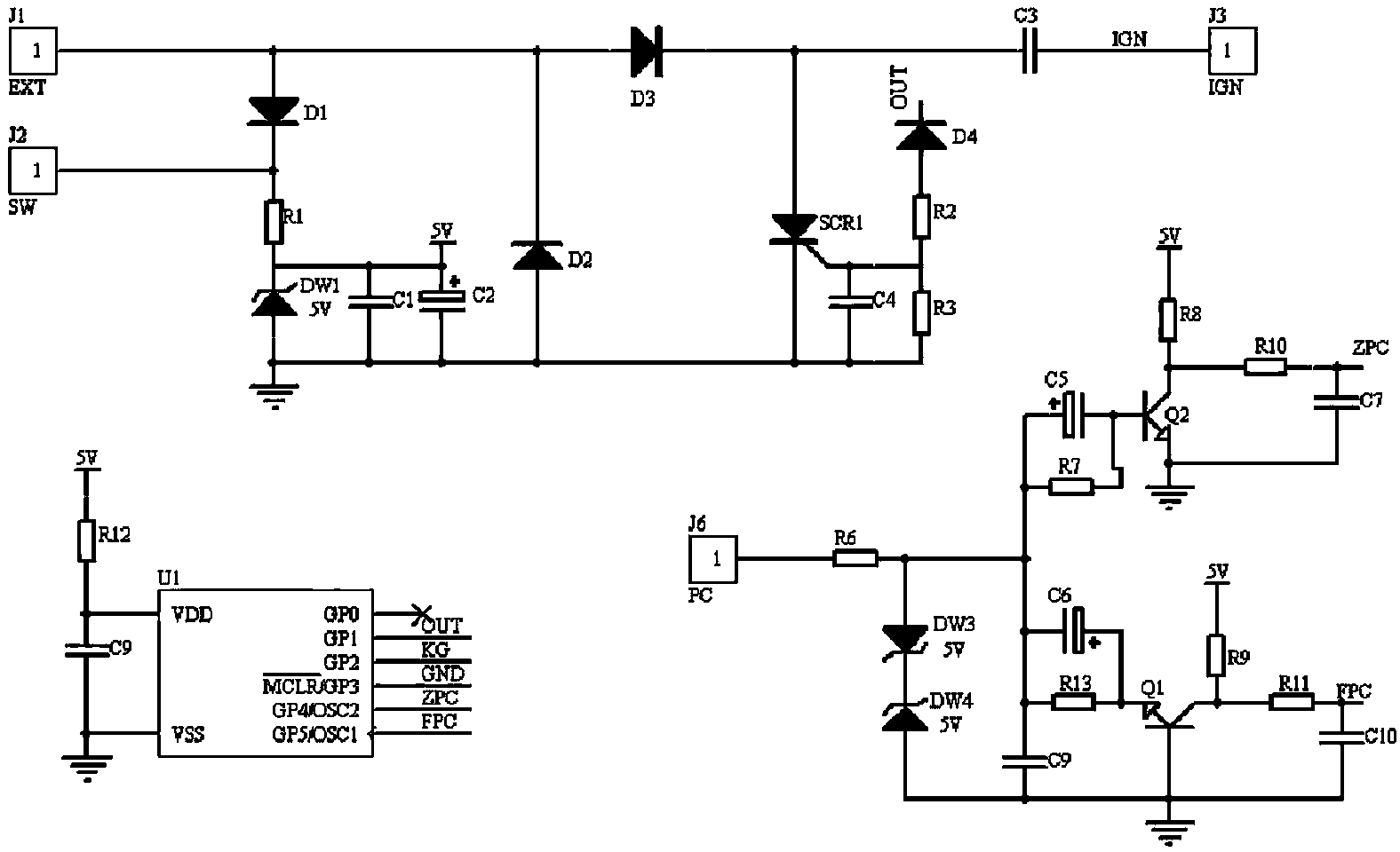
[0018] as attached figure 1 As shown, the integrated igniter control circuit of the present invention provides alternating current through the igniter control circuit to realize the ignition of the ignition coil by the magneto. The igniter control circuit includes a microchip, and the microchip is connected with the output end of the ignition coil, wherein the positive pulse signal When it arrives, ZPC provides a signal to the single-chip microcomputer. When the negative pulse arrives, FPC provides a signal to the single-chip microcomputer. The single-chip microchip processes the ZPC and FPC signals to output the OUT signal, thereby controlling the thyristor SCR1 to discharge positively, so that the capacitor C3 stores energy. Release, so as to provide energy to the ignition coil, and the ignition coil transforms the low voltage (400V) into a high voltage (21KV) discharge, ignites the oil-gas mixture in the gasoline engine, and achieves the purpose of ignition;

[0019] The mi...


PUM


Abstract

The invention discloses an integrated igniter control circuit; a magnetor provides alternating current, and then an ignition coil ignites through the integrated igniter control circuit. The integrated igniter control circuit comprises a microchip; the control circuit is connected to the output end of the ignition coil; when a positive pulse signal arrives, ZPC provides the signal to a single chip microcomputer; when a negative pulse signal arrives, FPC provides the signal to the single chip microcomputer; the single chip microcomputer processes the ZPC and FPC signal by the microchip to output an OUT signal so as to control a silicon controlled SCR1 to discharge positive electricity, so that energy stored in the capacitor C3 is released, and thereby the purpose of providing energy to the ignition coil is achieved, and low voltage (200V) is transformed to be high voltage (21KV) by the ignition coil to discharge to ignite oil and gas mixture in a gasoline engine, thus achieving the purpose of ignition; the microchip is added at the control part of the igniter, the igniter is under programmed control in a CD1 energy storage mode, and a curve for advance angles of ignition is traced out through programming according to power consumption of the engine, so that oil consumption is saved and ignition energy is large.

Description

technical field [0001] The invention relates to an igniter control circuit, in particular to an integrated igniter control circuit. Background technique [0002] The current igniter adopts the working method of analog or digital ignition control and high voltage separation. The traditional method consumes more energy and has less ignition energy. Contents of the invention [0003] In order to solve the above problems, an integrated igniter control circuit is provided. [0004] The purpose of the present invention is achieved in the following manner: the integrated igniter control circuit of the present invention provides alternating current through the igniter control circuit to realize ignition coil ignition by the magneto, and the igniter control circuit includes a microchip, and the control circuit It is connected to the output terminal of the ignition coil. When the positive pulse signal arrives, the ZPC terminal provides a signal to the single-chip microcomputer. Wh...

Claims


Application Information

Patent Timeline
Patent Type & Authority Applications(China)
IPC IPC(8): F02P5/15
Inventor 唐甲兵
Owner CHONGQING HUARI ELECTRICAL GOODS DEV
Why Eureka
Try Eureka