Indirect heat exchange type ice crystal spread-resistant device

A heat exchange and ice crystal technology, which is applied in the field of indirect heat exchange anti-ice crystal spreaders, can solve the problems of interruption of ice making cycle, freezing heat exchanger, etc., and achieve the effect of convenient connection

Inactive Publication Date: 2011-04-13
GUANGZHOU SENYO THERMAL STORAGE TECH
4 Cites 4 Cited by

AI-Extracted Technical Summary

Problems solved by technology

In a dynamic ice-making system, a large number of ice crystals in the ice slurry generator have a strong tendency to propagate upstream along the supercooled water pipe (subcooled heat exchang...

Abstract

The invention discloses an indirect heat exchange type ice crystal spread-resistant device. The indirect heat exchange type ice crystal spread-resistant device comprises a jet pipe and a heat exchange pipe, wherein the jet pipe comprises a speed-increasing section and a jet section; the speed-increasing section is arranged at the rear end of the jet pipe and the jet section is arranged at the front end of the jet pipe; the heat exchange pipe is sleeved outside the jet section of the jet pipe; the heat exchange pipe and the jet section form a heat exchange structure; a heat exchange cavity is formed in the heat exchange pipe; a heat exchange inlet and a heat exchange outlet are arranged on the heat exchange pipe; and the heat exchange cavity is communicated with the outside through the heat exchange inlet and the heat exchange outlet. The indirect heat exchange type ice crystal spread-resistant device has a simple structure and can effectively block the quick and reverse spread of ice crystals.

Application Domain

Technology Topic

EngineeringIce crystals +1

Image

  • Indirect heat exchange type ice crystal spread-resistant device
  • Indirect heat exchange type ice crystal spread-resistant device
  • Indirect heat exchange type ice crystal spread-resistant device

Examples

  • Experimental program(1)

Example Embodiment

[0029] The embodiments of the present invention will be described in detail below in conjunction with the drawings:
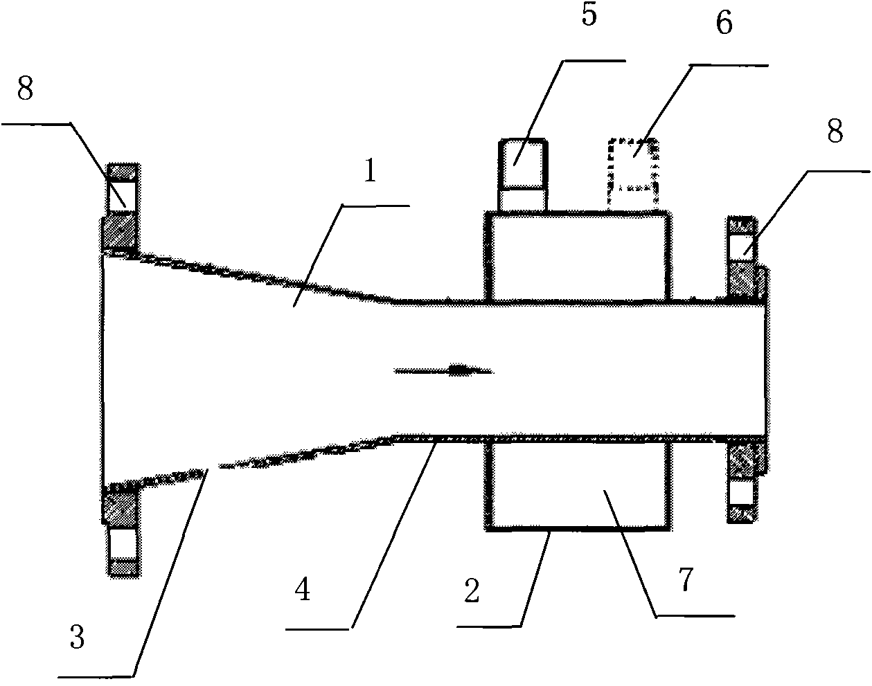
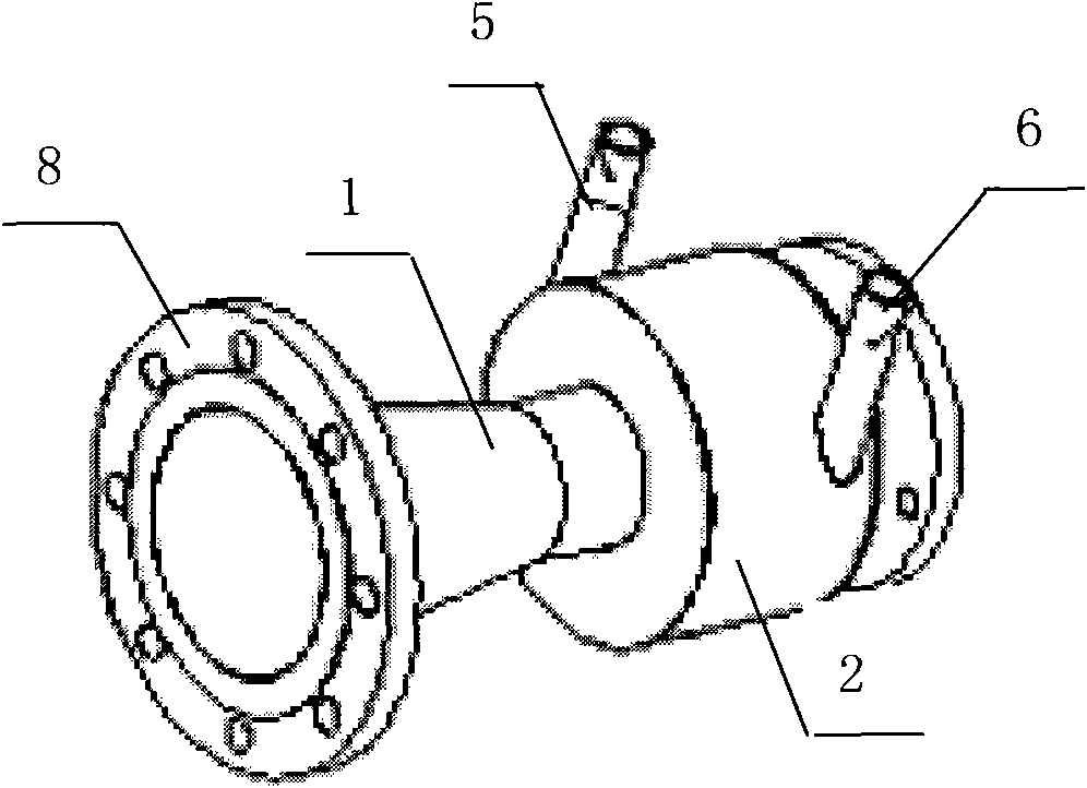
[0030] Such as figure 2 , image 3 As shown, an indirect heat exchange type anti-icing crystal propagator includes a jet tube 1 and a heat exchange tube 2. The jet tube 1 includes a speed-increasing section 3 at the rear end and a jet section 4 at the front end. The heat exchange tube 2 is sheathed on the jet tube The jet section 4 of 1 and the jet section 4 form a heat exchange structure. The heat exchange tube 2 is a heat exchange cavity 7. The heat exchange tube 2 is provided with a heat exchange inlet 5 and a heat exchange outlet 6, and the heat exchange cavity 7 passes heat exchange The inlet 5 and the heat exchange outlet 6 communicate with the outside.
[0031] Among them, the jet tube 1 and the inner wall of the flow cavity wall are provided with a hydrophobic coating; the cross-sectional area of ​​the front end of the jet tube 1 is smaller than the cross-sectional area of ​​the rear end, and the jet tube 1 is horn-shaped; the tube at the rear end of the speed increasing section 3 A connecting flange 8 is provided at the front end of the nozzle and the jet section 4. The heat exchange tube 2 has a ring shape, and an annular cavity is formed in the heat exchange tube 2. The annular cavity surrounds the jet section 4 of the jet tube 1 and is arranged coaxially with the jet tube 1.
[0032] Such as figure 1 Shown is the operating system diagram of the subcooled water dynamic ice storage ice making process. The low temperature water (such as 0°C) taken out from the ice storage tank is sent to the subcooling heat exchanger through the water pump, and it becomes Sub-cooled water below 0°C (such as -2°C) but still in liquid form. After the above-mentioned sub-cooled water is removed from the outlet of the sub-cooling heat exchanger, it enters the anti-icing crystal propagator described in this embodiment, and then passes through the anti-icing crystal propagator. Enter the ice slurry generator to release the supercooling state, generate ice slurry and send it back to the ice storage tank. The ice slurry is naturally stratified in the ice storage tank due to the difference in ice water density. The ice floats on the upper layer, and the water sinks in the lower layer. The water continues to be circulated and sent to the subcooling heat exchanger, and the cycle is repeated, the ice storage capacity continues to increase, until the storage is full and the machine stops.
[0033] In summary, the advantages of this embodiment are:
[0034] 1. When the supercooled water enters the jet flow section 4 from the speed increasing section 3, its flow rate increases. The supercooled water with a higher flow rate enters the ice slurry generator through the jet flow section 4. When the ice crystals in the ice slurry generator propagate upstream to this implementation For example, in the case of the anti-icing crystal propagator, a large number of ice crystals are generated on the inner wall of the jet section 4 of the jet tube 1 and the area close to the inner wall. At this time, because the heat exchange tube 2 is provided on the outer wall of the jet section 4 of the jet tube 1, the heat exchange tube 2 The water temperature of the heat exchange tube 2 is high, and the water in the heat exchange tube 2 exchanges heat with the jet tube 1, so that the ice crystals contacting the inner wall of the jet tube 1 jet section 4 quickly melt, so that the ice crystals close to the inner wall of the jet tube 1 jet section 4 and the tube inner wall The adhesion force of the ice crystals is greatly weakened, and the ice crystals flow downstream quickly under the scouring of the high-speed supercooled water in the jet section 4 of the jet tube 1, avoiding the propagation of ice crystals upstream;
[0035] 2. Since the inner wall of the jet tube 1 and the flow chamber wall are provided with a hydrophobic coating, even if ice crystals adhere to the inner wall of the jet tube 1 and the flow chamber wall, because of its small adhesion, as long as the flow rate of the supercooled water is large enough, The ice crystals can be blown off the wall and flow towards the front;
[0036] 3. The heat exchange tube 2 is sheathed on the jet section 4 of the jet tube 1, and surrounds the periphery of the jet section 4, so that the heat exchange tube 2 and the jet section 4 form a uniform heat exchange;
[0037] 4. Connecting flanges 8 are installed at the rear end of the speed increasing section 3 and the front end of the jet section 4, making it easier to connect with other pipelines of the system.
[0038] The above are only specific embodiments of the present invention and do not limit the protection scope of the present invention; any replacement and improvement made on the basis of not violating the concept of the present invention shall fall within the protection scope of the present invention.

PUM

no PUM

Description & Claims & Application Information

We can also present the details of the Description, Claims and Application information to help users get a comprehensive understanding of the technical details of the patent, such as background art, summary of invention, brief description of drawings, description of embodiments, and other original content. On the other hand, users can also determine the specific scope of protection of the technology through the list of claims; as well as understand the changes in the life cycle of the technology with the presentation of the patent timeline. Login to view more.

Similar technology patents

Pressure-balancing valve for irrigation system

Owner:INST OF GENETICS & DEVELOPMENTAL BIOLOGY CHINESE ACAD OF SCI

Classification and recommendation of technical efficacy words

Why Eureka
Try Eureka