
Fatigue driving monitoring method

A fatigue driving and driver technology, applied in the field of fatigue driving monitoring, can solve the problems of low monitoring efficiency, high probability of false detection, alarm delay, etc., to improve reliability and safety, fast monitoring speed and accuracy high effect

Inactive Publication Date: 2011-04-13
华南理工大学广州汽车学院
View PDF4 Cites 14 Cited by
  • Summary
  • Abstract
  • Description
  • Claims
  • Application Information

AI Technical Summary

Problems solved by technology

[0003] At present, a large number of fatigue driving monitors are mainly contact-type, which monitor the driver's fatigue state by detecting the driver's physiological signals, such as placing electrodes on the head to monitor EEG signals or ECG signals, etc. This monitoring method is easy Interference from the external environment, and differences between different drivers will also affect the monitoring results, resulting in low monitoring efficiency
At the same time, it is in contact with the driver's body and affects the driver's behavior. The real-time performance is not high, and it leads to alarm delay, which restricts its promotion and application.
[0004] For the non-contact technology currently used, most of them process the driver’s facial image information collected by the camera to determine whether the driver is fatigued, and the image processing technology is purely dependent on training (such as Adaboost training). method) for target recognition using features (such as Haar features), the monitoring efficiency is not high, and the probability of false detection is high

Method used


Image

  • Fatigue driving monitoring method
  • Fatigue driving monitoring method
  • Fatigue driving monitoring method

Examples


Embodiment Construction

[0020] Embodiments of the present invention will be described in detail below in conjunction with the accompanying drawings.

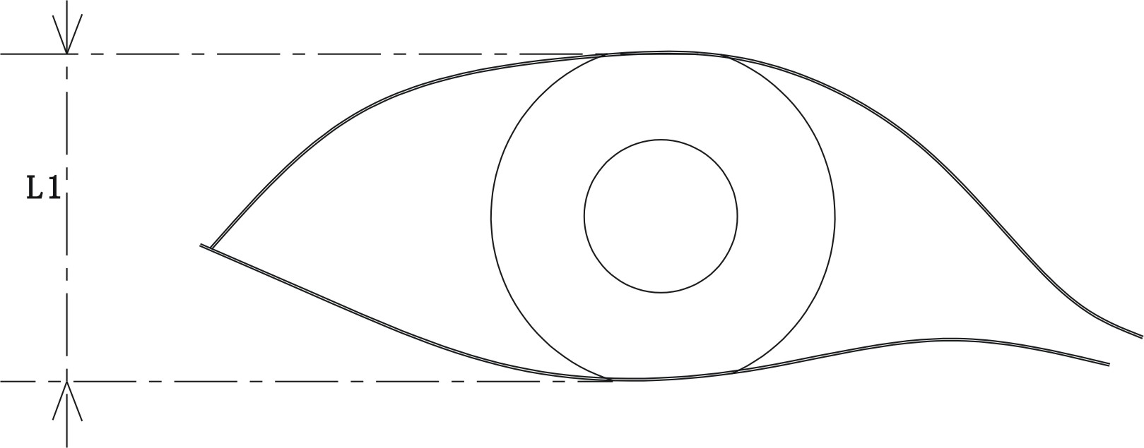
[0021] A fatigue driving monitoring method, the method comprising the steps of: A, the camera captures an image, and filters the captured image through a classifier in the monitor, and the image passed through the classifier is an eye image; B, analyzing After filtering the eye image, find the maximum distance L1 between the upper and lower points of the eyeball within the set time (such as figure 1 shown); C. Monitor the driver's eyeball and calculate the distance L2 between the upper and lower points of the driver's eyeball within the set time (such as figure 2 shown) and the maximum distance L1, if the difference exceeds the set range, an alarm will be processed.

[0022] Wherein, the classifier includes a first-level classifier, a second-level classifier, and a third-level classifier. In the step A, after the camera captures the image, it is firs...


PUM


Abstract

The invention discloses a fatigue driving monitoring method, which comprises the following steps of: A, acquiring images by using a camera, and filtering the acquired images through a classifier in a monitor, wherein the image which passes through the classifier is an eye image; B, analyzing the filtered eye image and finding the maximum distance L1 between the upper and lower points of an eyeball in set time; C, monitoring the eyeball of a driver, calculating the difference of the distance L2 between the upper and lower points of the eyeball and the maximum distance L1 in the set time, and alarming if the difference exceeds a set range. The monitoring method has higher accuracy.

Description

technical field [0001] The invention relates to a fatigue driving monitoring method. Background technique [0002] Globally, driver fatigue driving has become one of the important reasons leading to traffic safety accidents. Traffic accidents have caused huge economic losses and casualties to the country, and increased social unrest. [0003] At present, a large number of fatigue driving monitors are mainly contact-type, which monitor the driver's fatigue state by detecting the driver's physiological signals, such as placing electrodes on the head to monitor EEG signals or ECG signals, etc. This monitoring method is easy Interference from the external environment, and differences between different drivers will also affect the monitoring results, resulting in low monitoring efficiency. At the same time, the contact with the driver's body affects the driver's behavior, the real-time performance is not high, and the alarm delay is caused, which restricts its popularization an...

Claims


Application Information

Patent Timeline
IPC IPC(8): G06K9/00G06K9/62G08B21/06
Inventor 姜立标马乐余建伟张殷华吴斌姜思羽
Owner 华南理工大学广州汽车学院
Learn More