
Drawer push interlocking mechanism

A technology of interlocking mechanism and drawer, which is applied in the direction of pull-out switchgear, switchgear, electrical components, etc., and can solve the problem that the transmission worm and the trough-shaped turbine block cannot be self-locked, easy to produce relative displacement interlocking mechanism, and there are potential safety hazards and other problems, to achieve the effect of preventing relative displacement, improving safety, and easy operation

Active Publication Date: 2011-04-13
渭南汇德电气有限公司
View PDF7 Cites 16 Cited by
  • Summary
  • Abstract
  • Description
  • Claims
  • Application Information

AI Technical Summary

Problems solved by technology

[0015] Furthermore, the present invention also solves the problem that the drive worm and the trough-shaped turbine block cannot be self-locked, and the relative displacement is easy to occur, and the interlock mechanism may be displaced under the action of an external force, which poses a safety hazard

Method used


Image

  • Drawer push interlocking mechanism
  • Drawer push interlocking mechanism
  • Drawer push interlocking mechanism

Examples


Embodiment Construction

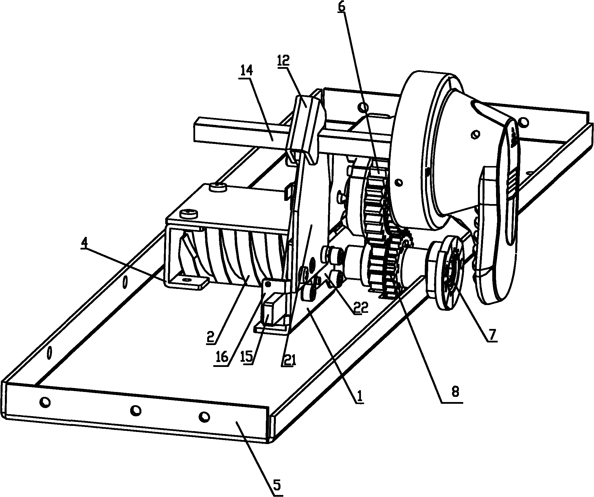
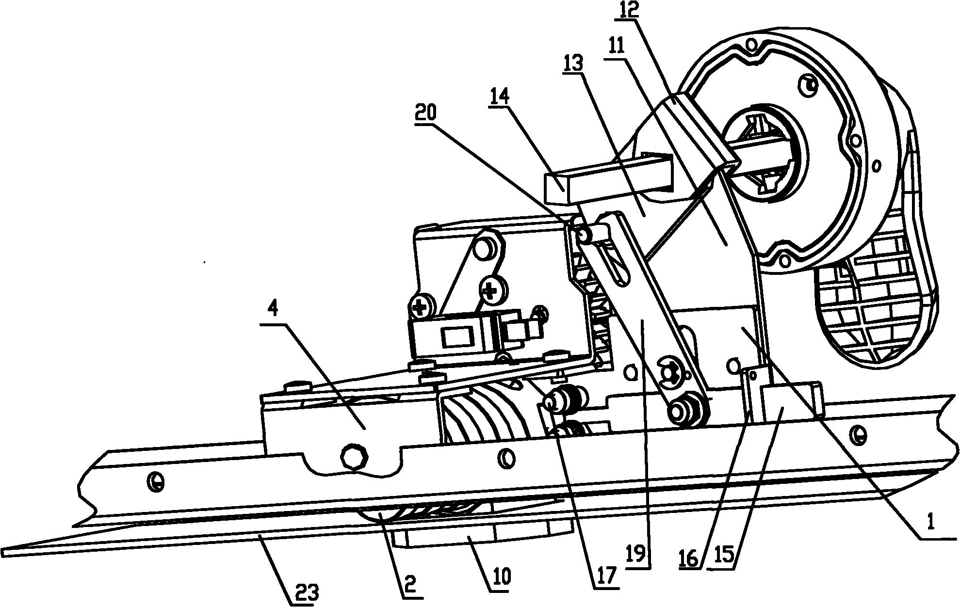
[0045] combine figure 1 and figure 2 As shown, the drawer push interlock mechanism of the present invention includes a push mechanism, a main drive wheel, a transmission positioning mechanism and a locking mechanism.

[0046]The propulsion mechanism includes a drive worm 2 mounted on the drawer bottom plate 5 through the front support 1 and the rear support 4, the drive worm 2 can engage with the trough-shaped turbine block 10 installed on the cabinet layer 23, and relative to the trough-shaped The turbine block 10 moves to realize the linear motion of the drawer relative to the cabinet body.

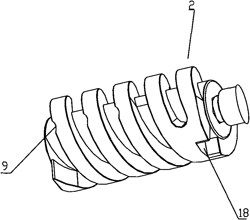
[0047] combine image 3 and Figure 4 As shown, the transmission worm 2 has a double-helix structure, which can reduce the number of rotations for adjusting the working position compared with the single-helix structure, and is easier to operate. Due to the large meshing angle between the transmission worm 2 and the trough-shaped turbine block 10, the transmission worm 2 is prone to...


PUM


Abstract

The invention relates to a drawer push interlocking mechanism, comprising a push mechanism, a main driving wheel, a transmission locating mechanism and a locking mechanism, wherein the interlocking mechanism comprises a locating locking bar, a force transfer mechanism and a position locking notch; the position lock notch is installed on the outer peripheral surface of a transmission worm rod; when the locating mechanism is at working position, the position locking notch is towards the inserting direction of the locating locking bar; the force transfer mechanism is connected with a rotating part assembled on a front bracket, and drives the locating locking bar to radially insert in the position locking notch to enter the locking position or enter the unlocking position far from the position locking notch. The position locking notch on the transmission worm rod is towards the inserting direction of the locating locking bar when the equipment is located at working position; therefore, the potential safety hazard caused by faulty operation of gate closing is prevented when the equipment is located at non-working position. Moreover, when the operation handle is located at gate closing position, the locating locking bar directly locks the transmission worm rod to prevent faulty operation of gate closing, thereby improving the mechanism safety.

Description

technical field [0001] The invention relates to a low-voltage withdrawable switchgear, in particular to a drawer push interlocking mechanism. Background technique [0002] The power distribution industry is a key industry in the country, and the reliability and safety of its equipment application is related to the development of the national economy and the safety of people's lives and property. The complete set of low-voltage switchgear equipment has a wide range of applications, but the professional level of the operators is uneven, and they do not fully understand the operating procedures of the equipment. As far as the low-voltage withdrawable switchgear is concerned, it includes at least three working positions: drawer and cabinet separation, experiment and connection, and two types of operations: opening and closing. The most prominent manifestation of misoperation is for the above three working positions. The operating procedures are unclear, such as opening and clos...

Claims


Application Information

Patent Timeline
IPC IPC(8): H02B11/133H02B11/173
Inventor 周金隆
Owner 渭南汇德电气有限公司
Features
  • Generate Ideas
  • Intellectual Property
  • Life Sciences
  • Materials
  • Tech Scout
  • Unparalleled Data Quality
  • Higher Quality Content
  • 60% Fewer Hallucinations
Learn More