Arrangement structure for power converter and control box in package-housed engine generator

A technology of engine drive and power converter, which is applied in the direction of machine/engine, engine cooling, engine components, etc., to achieve the effect of improving maintenance

Inactive Publication Date: 2011-04-13
YANMAR CO LTD
View PDF9 Cites 6 Cited by
  • Summary
  • Abstract
  • Description
  • Claims
  • Application Information

AI Technical Summary

Problems solved by technology

In this way, since the inverters and control panels are distributed on the side and front of the case, it is inco

Method used


Image

  • Arrangement structure for power converter and control box in package-housed engine generator
  • Arrangement structure for power converter and control box in package-housed engine generator
  • Arrangement structure for power converter and control box in package-housed engine generator

Examples


Embodiment Construction

[0046] Hereinafter, embodiments of the present invention will be described with reference to the drawings.

[0047] Figure 1 to Figure 8 One embodiment of the present invention employed in the cogeneration device 1 is shown. In addition, the combined heat and power device 1 is a power generation system in which an external commercial power supply and a generator are connected to a power transmission system to a power consumer (load), supplies the required power of the load, and recovers the power generated by the power generation. A system that rejects heat and utilizes this recovered heat.

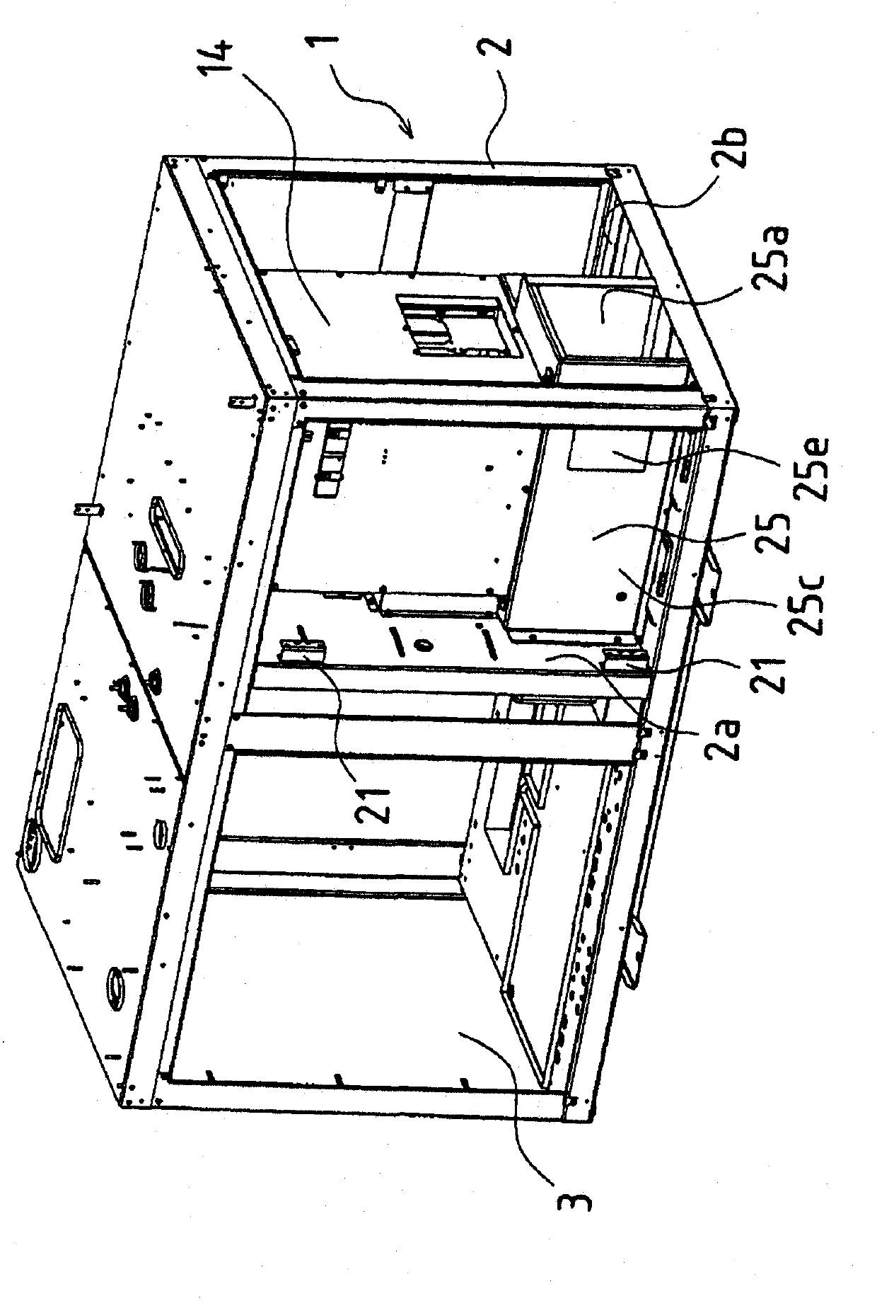
[0048] Figure 7 is a front perspective view showing a combined heat and power plant, Figure 8 It is a rear perspective view showing the cogeneration device. Such as Figure 7 and Figure 8 As shown, the cogeneration device 1 of the present embodiment includes a housing 2 formed in a substantially rectangular parallelepiped. The inside of the housing 2 is divided into upper and l...


PUM


Abstract

In a package-housed engine generator wherein an engine (10), a generator (11) driven by the engine, a power converter (14) that converts the generated power to a prescribed frequency, and a control box (17) that incorporates a control circuit board (16) for a radiator fan or another auxiliary part, are housed in a package (2), the control box and the power converter are arranged overlaid in that order in the inward direction relative to the open side of the package, and hinges (21) are provided on one edge of the control box to enable the control box to rotate.

Description

technical field [0001] The present invention relates to an arrangement structure of a control box and a power converter in a case-housing type engine-driven generator used in a cogeneration device and the like. Background technique [0002] At present, the case-housing type engine-driven generators used in combined heat and power devices, etc., house the engine in the case, the generator driven by the engine, the converter (power converter) that converts the generated power to a predetermined frequency, and the built-in heat sink. The control panel (control box) of the control board of the device such as the fan. [0003] Furthermore, the following disclosure discloses a structure in which such an engine, a generator, etc. are housed in a casing, and in order to improve the maintainability of the built-in equipment, the inverter is arranged in the rotary type at the lower part of the casing. Door (storage box) (for example, refer to Patent Document 1). [0004] Patent Docu...

Claims


Application Information

Patent Timeline
IPC IPC(8): F02B63/04
CPCF02B63/04F02B63/044F02B2063/045F01P2001/005
Inventor 川北启辅天川章平稻吉和敏
Owner YANMAR CO LTD
Why Eureka
Try Eureka