
Self-locking type invisible pulling head

An invisible slider and self-locking technology, applied in the direction of sliding fastener components, applications, fasteners, etc., can solve the problems of inconvenient mechanized automatic assembly, small size, etc., to facilitate automatic assembly, reduce assembly procedures, and stable operation Effect

Active Publication Date: 2011-04-20
成都浔兴拉链科技有限公司
View PDF1 Cites 8 Cited by
  • Summary
  • Abstract
  • Description
  • Claims
  • Application Information

AI Technical Summary

Problems solved by technology

The size of the cover plate is also relatively small, which makes the slider not easy to realize mechanized automatic assembly

Method used


Image

  • Self-locking type invisible pulling head
  • Self-locking type invisible pulling head
  • Self-locking type invisible pulling head

Examples


Embodiment Construction

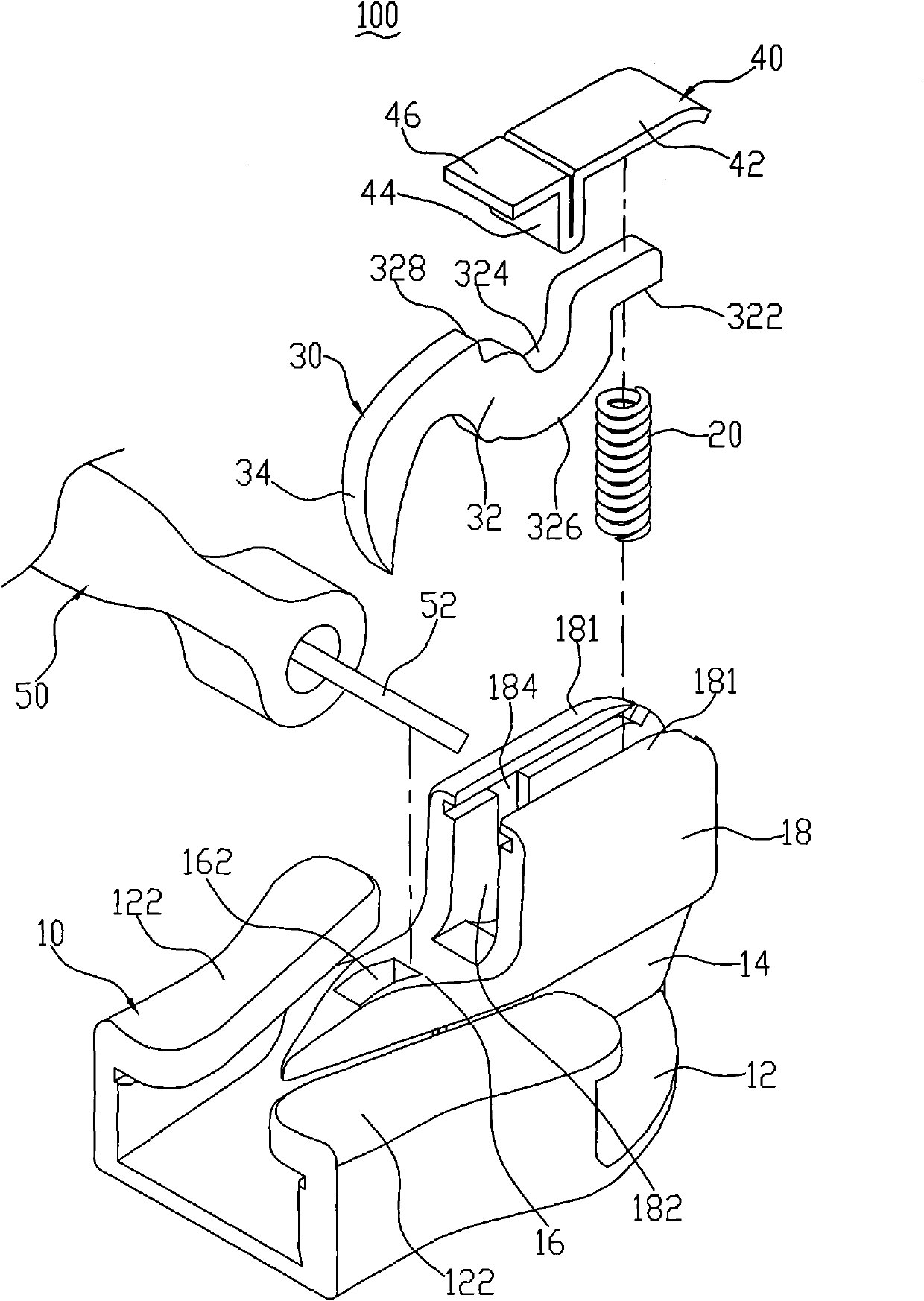
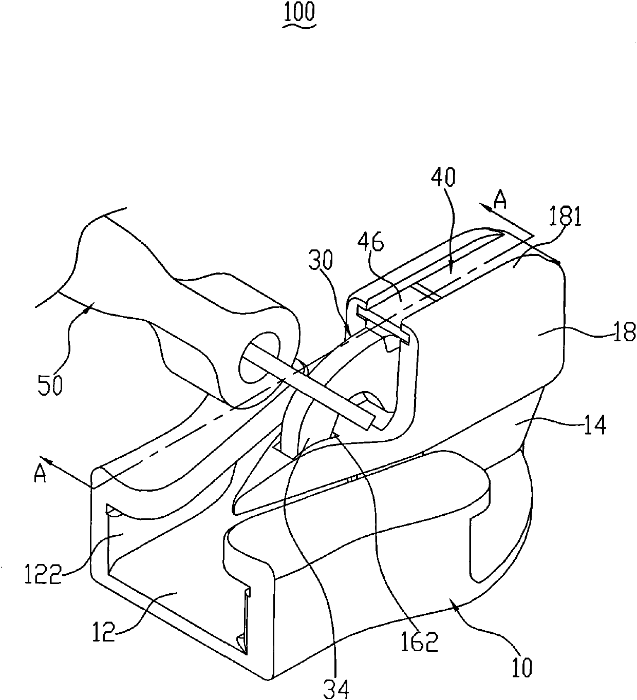
[0036] figure 1 It is a three-dimensional exploded view of the first embodiment of the invisible slider of the present invention. The invisible slider 100 includes a sliding block 10 , a spring 20 , a hook 30 , a pressed part 40 and a pull piece 50 . The spring 20, the horse hook 30, the pressed part 40 and the pull tab 50 are sequentially assembled on the slider 10 to form the invisible slider 100 (such as figure 2 shown). The slider 10 is integrally die-cast from zinc alloy.

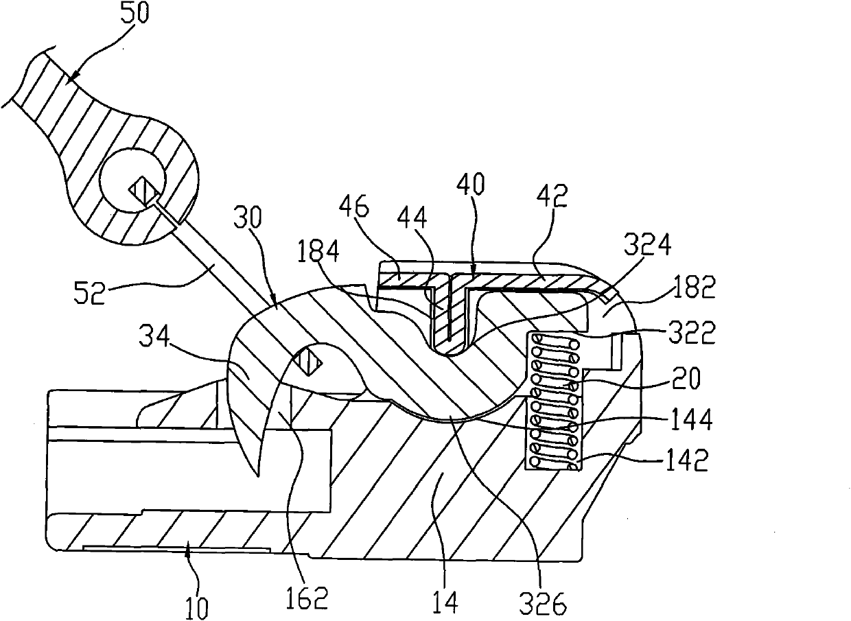
[0037] Please refer to figure 1 and image 3 , the pressed part 40 is integrally formed by a rectangular metal sheet (not shown) through a cold stamping process. The pressed part 40 is roughly "T"-shaped in side view. The pressed part 40 includes two fixed sections 42, 46 and a pressed section 44. When forming, the metal sheet is first folded in half along a predetermined position, and then the two ends of the folded metal sheet are bent 90 degrees respectively, thereby forming the Two fixing s...


PUM


Abstract

The present invention relates to a self-locking type invisible pulling head, comprising a slide block, an elastic element, a horse hook and a suppressed component. The slide block comprises a lower plate, a guide pillar, an upper plate and a connecting pillar. An accepting groove is provided on the connecting pillar. The horse hook comprises a pivoted part and a hook part. The pivoted part of the horse hook and the elastic element are arranged in the accepting groove of the connecting pillar. The front of the pivoted part abuts against the elastic element. The suppressed component comprises fixed sections and a suppressed section. The fixed sections are fixed onto the connecting pillar and suppress the suppressed section. A pivot groove is arranged on the top end of the pivoted part of the horse hook corresponding to the suppressed section. The suppressed section has a plate-shaped structure arranged downwardly. A pivot block is arranged at the bottom of the pivoted part of the horse hook corresponding to the pivot groove. During the operation, the horse hook rotates around the suppressed section through the pivot groove. The pulling head has the advantages of simple structure, stable operation and convenient automated assembly.

Description

technical field [0001] The invention relates to an invisible slider, in particular to a self-locking invisible slider. Background technique [0002] At present, there are many kinds of invisible sliders. These invisible sliders make the chain teeth of the nylon zipper concentrate on one side of the chain belt when the nylon zipper is closed, while the other side of the chain tape has no chain teeth, thereby hiding the chain teeth of the nylon zipper. The invisible slider is a relatively special product, and its uniqueness determines that it has less space for installing the hook and spring, and at the same time, it is more difficult to realize automatic assembly. For example, the Chinese Utility Model Patent No. 01218606.6 announced on February 27, 2002 discloses a slider device for a hidden zipper, which includes: a slider body, the slider body has a guide edge, and the guide edge It has a pair of separated walls, a groove is formed between the pair of walls; each of the ...

Claims


Application Information

Patent Timeline
Patent Type & Authority Applications(China)
IPC IPC(8): A44B19/26
Inventor 骆燕明
Owner 成都浔兴拉链科技有限公司
Learn More