

Equipment and method for degassing regenerated catalyst
A technology for catalyst regeneration and degassing, which is applied in chemical instruments and methods, catalyst regeneration/reactivation, physical/chemical process catalysts, etc. Achieve the effect of reducing the catalyst loss of the device and reducing the hydrothermal deactivation
Active Publication Date: 2011-04-20
CHINA PETROCHEMICAL CORP +1
View PDF2 Cites 1 Cited by
- Summary
- Abstract
- Description
- Claims
- Application Information
AI Technical Summary
Problems solved by technology
[0009] In summary, CN 1226100C discloses a method for removing flue gas with a tray-type internal component regeneration agent, which is a single-stage bed degassing, and the degassing efficiency is low; CN 100351016C discloses a multi-stage stripping method although it is a catalyst , but the degassing gas of the next section is mixed with the newly introduced degassing medium of the previous section, which reduces the degassing (mass transfer) driving force of the previous section; US 66562736 B1 discloses a method for multi-section stripping chambers, and the next section The degassed gas is not in contact with the degassed medium in the previous stage, but the amount of degassed medium introduced into each stage and the type of degassed bed are not explained.
Method used
View moreImage
Smart ImageViewing Examples

Examples
specific Embodiment
[0042] The following are the design and operating parameters of the high-efficiency degassing tank for the regenerated catalyst of a catalytic cracking unit:
[0043] serial number
[0044] 16
[0045] Note: Degassing efficiency (η) = (inlet catalyst flue gas flow rate - outlet catalyst flue gas flow rate) / inlet catalyst flue gas flow rate.
Login to View More PUM
 Abstract
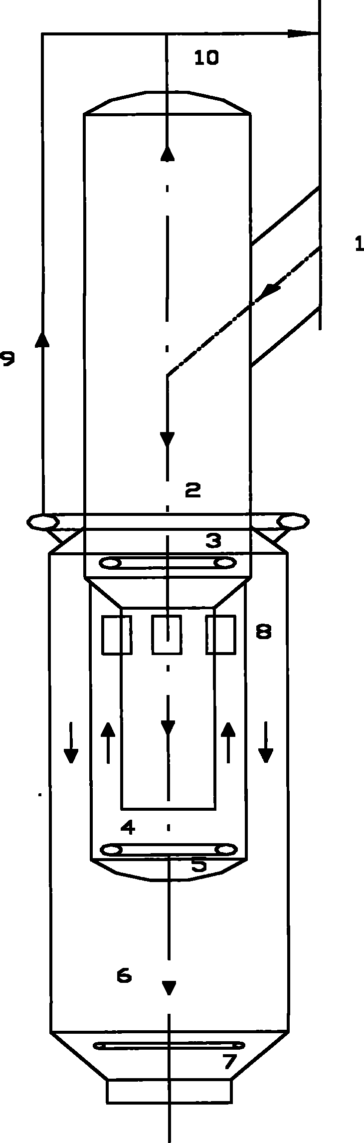
The invention relates to equipment and a method for degassing a regenerated catalyst, which belongs to the technical field of efficient degassing of the regenerated catalyst which is regenerated by singeing. The technology is characterized in that: the regenerated catalyst from a regenerator is fed into a three-stage degassing bed; a fresh degassing medium is injected into each stage of degassing bed; each stage of degassed gas is separately discharged; and the degassing medium injected into each stage of degassing bed is gradually reduced so as to form different fluidization forms of each stage of catalyst bed layer, so that the regenerated catalyst can effectively contact the fresh degassing medium at each stage, the mass transfer driving force for degassing is improved, and the degassing effect is improved.
Description
technical field [0001] The invention belongs to the high-efficiency degassing tank technology of a regenerated catalyst regenerated by burning, and specifically relates to processes such as catalytic cracking, methanol conversion to olefins, and the like. Background technique [0002] During the recycling process of the regenerated catalyst, it is inevitable to entrain the regenerator non-hydrocarbon gas (mainly including N 2 , CO 2 , CO, O 2 etc., also known as flue gas), this gas exists between the catalyst particles and in the pores of the catalyst, the gas between the catalyst particles is easier to remove, and the gas in the catalyst pores is more difficult to remove. For catalytic cracking equilibrium catalyst, when its pore volume is 0.24-0.4ml / g, its apparent density is 500kg / m 3 At this time, the amount of gas in the catalyst pores accounts for 15-25v% of the total gas entrainment, and the entrainment between catalyst particles is 75-85v%. [0003] Due to the lo...
Claims
Login to View More Application Information
Patent Timeline
 Patent Type & Authority Applications(China)
IPC IPC(8): B01J38/06
Inventor 吴雷余龙红闫涛居颖
Owner CHINA PETROCHEMICAL CORP