Blower fan

A blower fan and fan frame technology, applied in the field of blower fans with air ducts, to achieve the effect of improving the convenience of use, improving the heat dissipation effect, and improving the heat dissipation effect

Active Publication Date: 2011-04-20
SUNONWEALTH ELECTRIC MACHINE IND
View PDF2 Cites 4 Cited by
  • Summary
  • Abstract
  • Description
  • Claims
  • Application Information

AI Technical Summary

Problems solved by technology

[0010] The purpose of the present invention is to improve the shortcomings of the above-mentio...

Method used


Image

  • Blower fan
  • Blower fan
  • Blower fan

Examples


Embodiment Construction

[0035] In order to make the above-mentioned and other objects, features and advantages of the present invention more comprehensible, the preferred embodiments of the present invention are specifically cited below, together with the accompanying drawings, as follows:

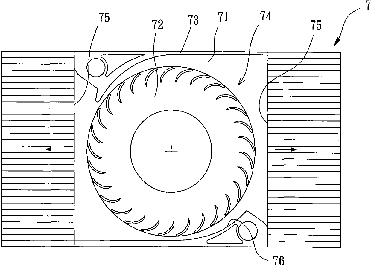
[0036] Please refer to Figure 4 and 5 As shown, the blower fan of the present invention includes a fan frame 1 , a fan wheel 2 and an air duct 3 . The fan frame 1 can be combined at a predetermined position of an electronic product (such as the surface of the motherboard inside the computer); the fan wheel 2 can be rotatably combined in the fan frame 1 to generate enough air volume for heat dissipation; the air duct 3 combined with the fan frame 1 to dissipate heat for several heat sources 4 at different positions inside the electronic product.

[0037] The fan frame 1 has a ring wall 11, the ring wall 11 surrounds and forms an accommodating space 111, and the fan frame 1 is provided with an air inlet 12 and a...


PUM


Abstract

Provided is a blower fan comprising a fan frame, an impeller and at least one air-guide duct. The fan frame is provided with an air inlet, an air outlet and the containing space. The air inlet and the air outlet are communicated with the containing space and the containing space can be divided into an air-out zone and a pressure accumulation zone. The impeller is arranged in the containing space. The at least one air-guide duct is used to combine the fan frame and to communicate with the containing space, wherein the at least one air-guide duct is provided with an air-in end and an air-out end with the air-in end placed at the pressure accumulation zone and the air-out end facing at least one heat source. Thereby, the blower fan is able to carry out heat radiation for several different positions by simultaneously using the air outlet and the at least one air-guide duct so as to produce better radiation effects.

Description

technical field [0001] The invention relates to a blower fan, in particular to a blower fan with an air duct. Background technique [0002] The existing blower fan has a fan frame, which is provided with an axial air inlet and a side air outlet, and a rotatable fan wheel is arranged inside the fan frame; The axial air inlet introduces airflow, and the airflow can be concentrated and discharged to a heat source through the lateral air outlet. Generally speaking, when the existing blowing fan is actually used for heat dissipation, the blowing fan must be installed at the peripheral position of the heat source, and the side air outlet must be directed towards the heat source, so that the heat loss of the heat source can be reduced. temperature. [0003] However, today's various electronic products may generate heat sources in several different locations during actual operation, for example: the motherboard, central processing unit, display card, etc. inside the computer will ...

Claims


Application Information

Patent Timeline
IPC IPC(8): F04D17/04F04D29/44
Inventor 洪银树李明聪李朝勋
Owner SUNONWEALTH ELECTRIC MACHINE IND
Why Eureka
Try Eureka