Drive circuit of adjustable power supply for ecological house

A driving circuit and ecological house technology, applied in the circuit field, can solve problems such as imperfect driving circuit system

Inactive Publication Date: 2011-04-20
SUZHOU HEXINMEI ELECTRONICS SCI & TECH CO LTD
View PDF4 Cites 2 Cited by
  • Summary
  • Abstract
  • Description
  • Claims
  • Application Information

AI Technical Summary

Problems solved by technology

[0003] But in the prior art, the driving circuit system of the adjustable power supply of the ecological house is not perfect yet.

Method used


Image

  • Drive circuit of adjustable power supply for ecological house
  • Drive circuit of adjustable power supply for ecological house

Examples


Embodiment Construction

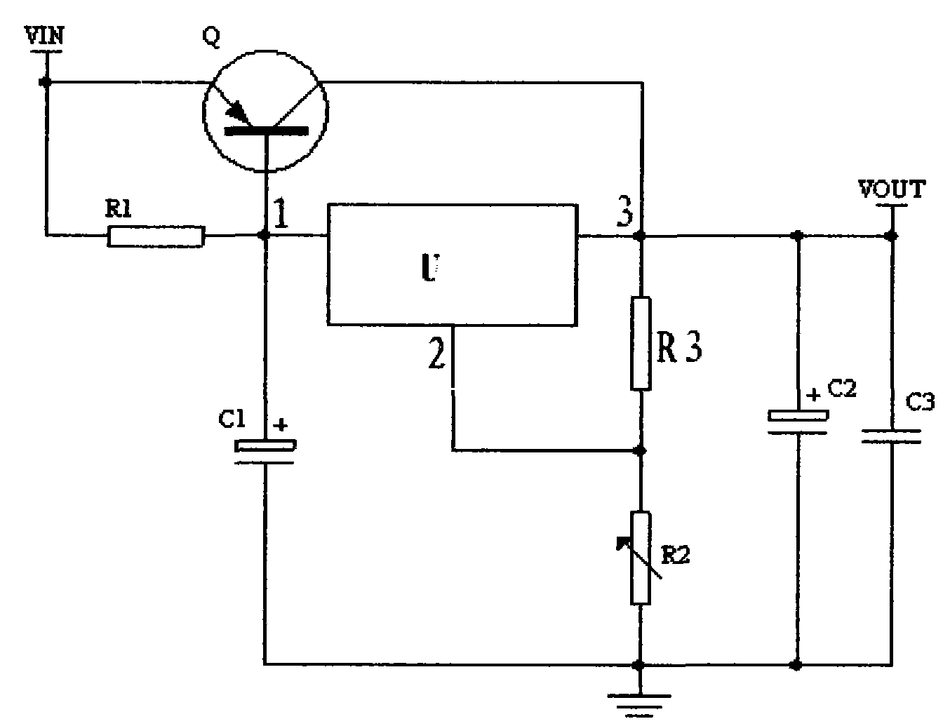
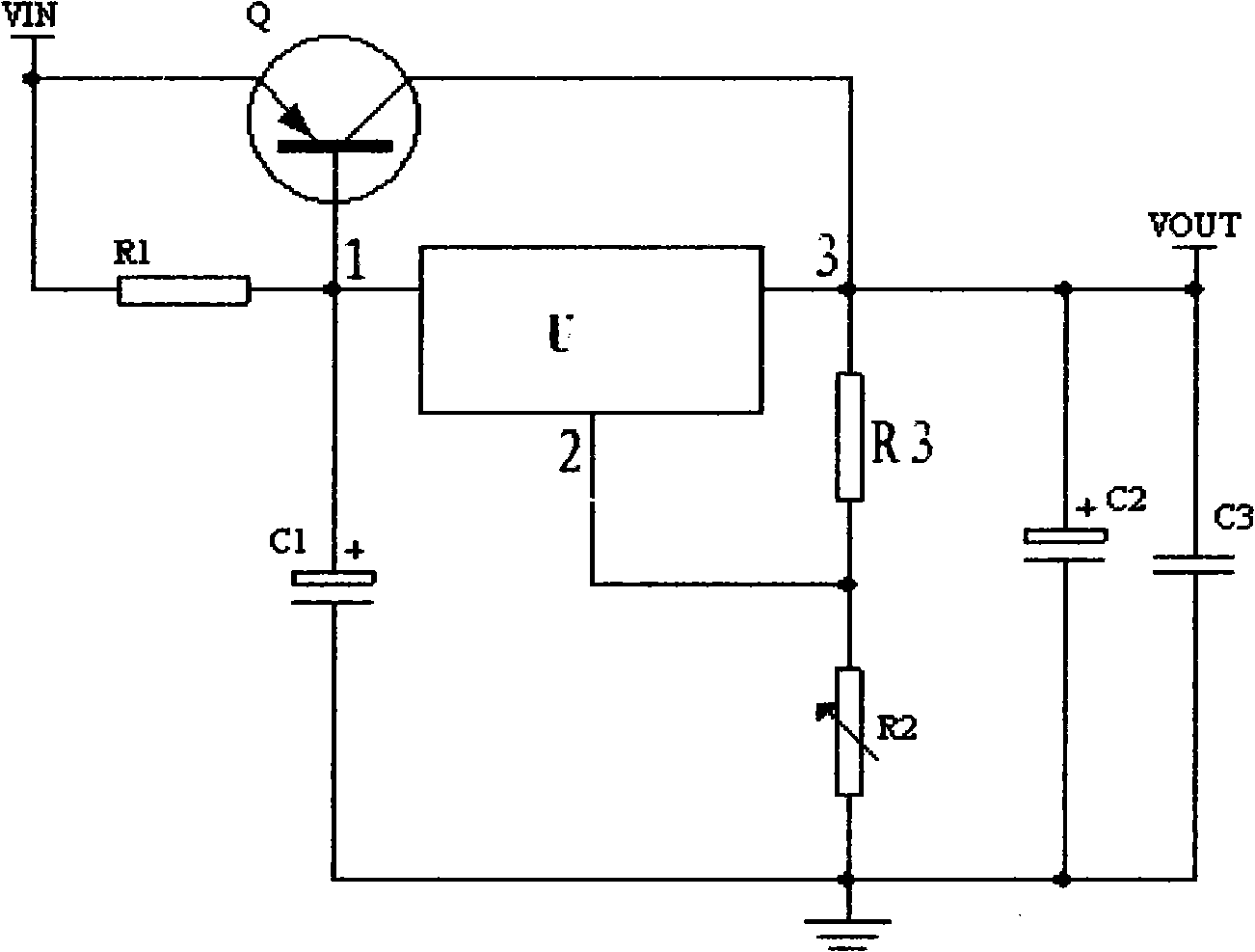
[0016] The schematic diagram of the drive circuit of the drive circuit of the adjustable power supply of this embodiment is shown in the accompanying drawings:

[0017] A driving circuit of a variable power supply of an ecological house of the present invention consists of a main control chip U, a voltage input terminal Vin, a triode Q, three resistors (R1-R3), three capacitors (C1-C3) and a voltage The output terminal Vout is connected,

[0018] The No. 1 port of the main control chip U is connected to the base of the triode Q, the resistor R1 is connected between the base and the emitter of the triode Q, and the emitter of the triode Q1 is connected to the supply voltage Vin,

[0019] The No. 1 port and No. 2 port of the main control chip U are connected across the series circuit of capacitor C1 and resistor R2. The positive pole of capacitor C1 is connected to No. 1 port of the electric control board U, and the negative pole is grounded.

[0020] The No. 2 port of the main...


PUM


Abstract

The invention relates to a drive circuit of an adjustable power supply for an ecological house, which is formed by connecting a main control chip U, a voltage input end Vin, a triode Q, three resistors (R1-R3), three capacitors (C1-C3) and a voltage output end. The drive circuit of the adjustable power supply has the beneficial effect that the resistors are adjusted to change the range of the voltage output, thereby realizing the adjustable function of the power supply.

Description

technical field [0001] The invention relates to the field of circuits, in particular to a drive circuit for an adjustable power supply of an ecological house. Background technique [0002] The design concept of the eco-house controller is to imitate the human body for a better life, and the rest environment emerges as the times require. It uses information electronics and other technologies to imitate the natural ecological environment, which can play the role of beauty, skin care, and health care. In this way, some existing practical technologies are integrated into a control system. The whole system is divided into three modules: the air conditioning control module, the central control block, and the human-computer interaction module. The three control modules realize mutual information through communication. transfer. [0003] But in the prior art, the driving circuit system of the adjustable power supply of the ecological house is not perfect. Contents of the inventio...

Claims


Application Information

Patent Timeline
Patent Type & Authority Applications(China)
IPC IPC(8): H02M3/06
Inventor 胡国良魏王江
Owner SUZHOU HEXINMEI ELECTRONICS SCI & TECH CO LTD
Why Eureka
Try Eureka