Method for reducing vibration and noise of permanent-magnet motor

A permanent magnet motor, noise technology, applied in the direction of torque ripple control, etc., can solve the problem that the unit shape optimization method does not establish a general priority criterion for the magnetic pole shape, the lack of an optimal segment angle, and the non-uniform distribution of the magnetic pole. Pole inclination, unit number optimization method does not give the slot/pole/phase number matching principle, etc., to achieve the effect of convenient parameter selection, vibration reduction and/or noise reduction, and vibration reduction

Active Publication Date: 2011-04-20
TIANJIN UNIV
View PDF3 Cites 16 Cited by
  • Summary
  • Abstract
  • Description
  • Claims
  • Application Information

AI Technical Summary

Problems solved by technology

[0020] The disadvantages of the above methods are: the unit number optimization method does not give a correct and complete slot/pole/phase number matching principle; the unit shape optimization method does not establish a general priority criterion for the magnetic pole shape; the unit position optimization method lacks the optimal The general principle of inter-segment angle, non-uniform magnetic pole distribution angle, and slot/pole inclination angle; while the optimal control method basically does not consider the influence of mechanical factors
[0027] (2) The existing litera

Method used


Image

  • Method for reducing vibration and noise of permanent-magnet motor
  • Method for reducing vibration and noise of permanent-magnet motor
  • Method for reducing vibration and noise of permanent-magnet motor

Examples


Embodiment Construction

[0044] Below in conjunction with specific embodiment, and with reference to accompanying drawing, the present invention will be further described:

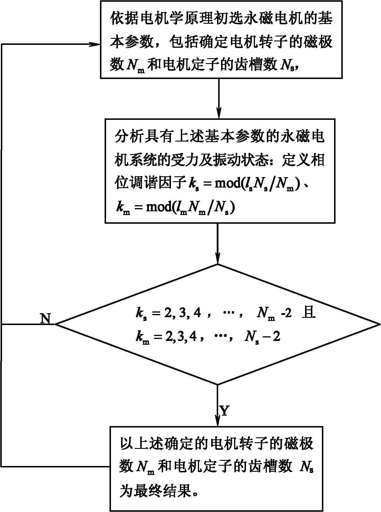
[0045] Such as figure 1 The shown method of the present invention for reducing the vibration and noise of the permanent magnet motor comprises the following steps: (1) according to the primary selection of the number of magnetic poles and the number of slots in the application; (2) judging the force and vibration of the permanent magnet motor State: if according to the formula k s =mod(l s N s / N m ) to get the phase tuning factor k s =0 and according to the formula k m =mod(l m N m / N s ) to obtain k m = 0, the permanent magnet motor will produce torque ripple; if the phase tuning factor k s = 1 or N m -1,k m = 1 or N s -1, permanent magnet motor will produce unbalanced magnetic pull; if k s =2,3,4,...,N m -2, and k m =2,3,4,...,N s -2, the permanent magnet motor will be in a state of force balance, where N m is...


PUM


Abstract

The invention discloses a method for reducing the vibration and the noise of a permanent-magnet motor, comprising the following steps of: (1) initially selecting a magnetic pole number and a tooth socket number according to application occasions; (2) judging the stress and vibration states of the permanent-magnet motor, wherein the permanent-magnet motor generates torque pulsation if a phase tuning factor ks=0 is solved according to a formula: ks=mod (lsNs/Nm) and km=0 is solved according to a formula: km=mod (lsNm/Ns), the permanent-magnet motor generates unbalanced magnetic pull if the phase tuning factor ks=1 or Nm-1 and km=1 or Ns-1, and the permanent-magnet motor is in a stress balance state if ks=2, 3, 4 to Nm-2 and km=2, 3, 4 to Ns-2; and (3) repeating calculation formulas of the corresponding stress and vibration states in the step (2) to select the sum of the magnetic pole number and the tooth socket number. The method can be used for selecting different parameters aiming at different occasions according to the mapping relation between the magnetic pole number and the tooth socket number of the permanent-magnet motor and the vibration and noise characteristics of the permanent-magnet motor, thereby realizing the vibration reduction and/or the noise reduction of the permanent-magnet motor.

Description

technical field [0001] The invention relates to a method for reducing vibration and noise, in particular to a method for reducing vibration and noise of a permanent magnet motor. Background technique [0002] Permanent magnet motor is a kind of electromechanical energy conversion device with magnetic field as the medium. It has the advantages of energy saving, environmental protection, simple structure and reliable operation. It has a wide range of applications. But in many important applications, vibration and noise levels have become important indicators of motor performance. [0003] Due to the pulsating excitation of the permanent magnet motor, it will inevitably generate vibration and noise, thus affecting the performance of the motor. For example, in digital copying equipment, the torque ripple of the motor will cause electrostatic latent images on the surface of the photoreceptor, thus affecting the copying quality. In high-speed disk drives, the vibration of the sp...

Claims


Application Information

Patent Timeline
IPC IPC(8): H02P6/10
Inventor 王世宇霍咪娜修杰王建刘建平
Owner TIANJIN UNIV
Why Eureka
Try Eureka