

Synchronous oscillator, clock recovery apparatus, clock distribution circuit, and multi-mode injection circuit
一种注入电路、同步振荡的技术,应用在同步装置、电脉冲发生器电路、产生/分配信号等方向,能够解决时钟信号与接收数据信号同步要耗时久、难以实现时钟恢复装置高速操作、不适突发数据传输等问题,达到增强持久性、增大操作速度、降低功耗的效果
Inactive Publication Date: 2011-04-20
SONY CORP
View PDF9 Cites 8 Cited by
- Summary
- Abstract
- Description
- Claims
- Application Information
AI Technical Summary
Problems solved by technology
[0005] However, these clock recovery schemes involve a problem that high-speed operation requires a phase comparator that operates at high speed, making it difficult to achieve high-speed operation of the clock recovery device
[0006] In addition, because these schemes are implemented based on negative feedback for locking with the received data signal, it takes a considerable time to synchronize the clock signal with the received data signal, making these schemes unsuitable for applications that need to be synchronized with the received data signal in a relatively short period of time. Transmission of burst data with data signal locked
Method used
View moreImage
Smart ImageViewing Examples


Examples
no. 3 approach
[0083] (3) Third embodiment (second exemplary configuration of clock recovery device)
no. 4 approach
[0084] (4) Fourth embodiment (third exemplary configuration of clock recovery device)
no. 5 approach
[0085] (5) Fifth embodiment (fourth exemplary configuration of clock recovery device)
[0086] (6) Sixth embodiment (first exemplary configuration of clock distribution circuit)
Login to View More PUM
 Abstract
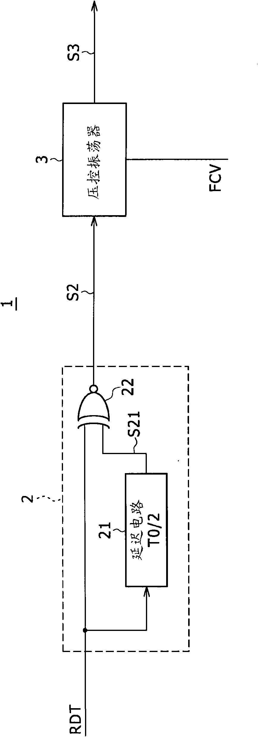
Disclosed herein is a synchronous oscillator including at least one injection circuit having an injection signal input terminal, an internal clock signal input terminal, and a clock output terminal, and at least one delay circuit cascaded to the injection circuit.
Description
Technical field [0001] The present invention relates to a synchronous oscillator, a clock recovery device, a clock distribution circuit and a multi-mode injection circuit for outputting a clock signal. Background technique [0002] Recently, in the field of digital transmission, the demand for high-speed and low-power transmission of large amounts of data has been increasing. For interfaces used for such data transmission, clock recovery devices are widely used. [0003] At the same time, due to the increased jitter component contained in the signal caused by the increased transmission rate, the ability to resist the jitter of the high-speed interface is desired. [0004] Clock recovery includes those based on PLL applications, as well as selecting or generating a clock with phase locked to the received data signal from a multi-phase clock signal. [0005] However, these clock recovery schemes involve the problem that high-speed operation requires a phase comparator that operates at ...
Claims
Login to View More Application Information
Patent Timeline
 Patent Type & AuthorityApplications(China)
IPC IPC(8): H03L7/099H03L7/06H04L7/033H03K3/03H03K3/356H03K5/13H03K19/20H03L7/00H03L7/08H04L7/02
CPCH03L7/0995G06F1/12H03L7/0807H03L7/0805H03K3/0315H03K5/13H03L7/00H03L7/02H04L7/033
Inventor丸子健一
OwnerSONY CORP