Method for operating a power tool, especially a hand-held power tool

A hand-held machine tool, machine tool technology, applied in the direction of manufacturing tools, metal processing machinery parts, metal processing equipment, etc.

Active Publication Date: 2011-04-20
ROBERT BOSCH GMBH
View PDF1 Cites 0 Cited by
  • Summary
  • Abstract
  • Description
  • Claims
  • Application Information

AI Technical Summary

Problems solved by technology

Although curves can be sawed more easily in this way, the adjustment possibility of the saw blade does not mean an adjustable degree of freedom during the sawing process, but a certain angle of the saw blade must be determined in advance

Method used


Image

  • Method for operating a power tool, especially a hand-held power tool
  • Method for operating a power tool, especially a hand-held power tool
  • Method for operating a power tool, especially a hand-held power tool

Examples


Embodiment Construction

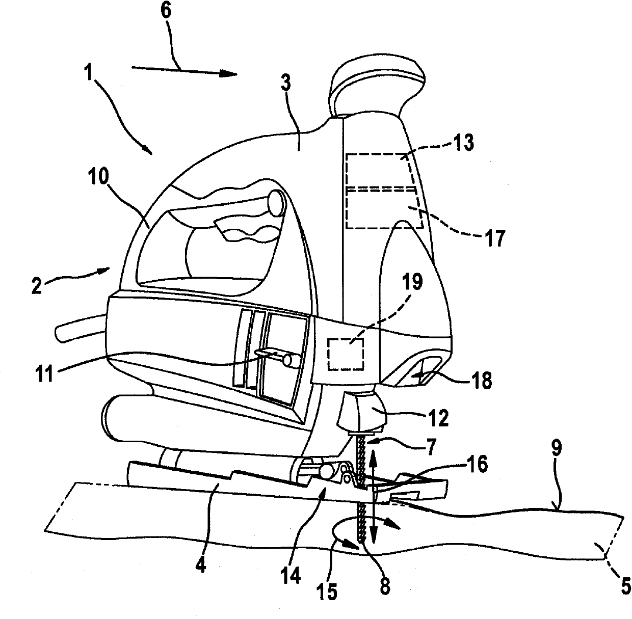
[0019] figure 1 Shown is a hand-held jigsaw 2, as an example of a power tool 1, which has in the housing 3 a saw blade 8 performing a reciprocating movement (as a working movement 7), which penetrates a base plate 4, which is in contact with the Shell 3 is connected. This base plate 4 rests on the workpiece 5 to be processed, wherein the jigsaw 2 is moved in the working direction 6 on or through the workpiece 5 . On the upper surface of the workpiece 5 , a contour line 9 represents the desired path, which serves as a marking or machining path, along which contour line 9 the saw blade 8 of the jigsaw 2 is to be guided.

[0020] The reciprocating movement of the saw blade 8 is produced by an electric drive motor housed in the housing 3 of the jigsaw 2 . On the housing 3 is located a grip 10 on which the power tool can be manually held and guided. For switching on and off, a manually operable switch is arranged in the side area of ​​the housing 3 .

[0021] The saw blade 8 , ...


PUM


Abstract

The invention relates to a method for operating a power tool (1), especially a hand-held power tool, whereby sensor signals of a sensor device (13) are subjected to a plausibility check prior to processing, an error signal being generated if a sensor signal is outside a defined normal range.

Description

technical field [0001] The invention relates to a method for operating a power tool, in particular a hand-held power tool. Background technique [0002] A hand-held motor-driven jigsaw is known from US 2005 / 0060896 A1, the saw blade of which is driven by an electric motor and performs a reciprocating movement. The saw blade is clamped or guided in the holder and can be locked in different angular positions about the longitudinal axis of the saw blade. To adjust to the desired angular position, loosen the bracket, adjust the saw blade to the new angular position, and then secure the bracket again. Even though curves can be sawed more easily in this way, the adjustment possibilities of the saw blade do not mean an adjustable degree of freedom during the sawing process, but rather a certain angle of the saw blade must be determined in advance. During the sawing process a constantly changing adaptation to the different radii to be sawn is not possible. Contents of the invent...

Claims


Application Information

Patent Timeline
IPC IPC(8): B23D59/00B23Q17/24
CPCB23D59/001
Inventor T・科德J・普拉策U・霍夫曼
Owner ROBERT BOSCH GMBH
Why Eureka
Try Eureka