
Device for generating energy in a rotating system

An electric energy and energy technology, applied in the field of electric energy generating devices, can solve problems such as unbalance, damaged components, adverse effects of stable rotation, etc., and achieve the effect of enhancing electric charge

Inactive Publication Date: 2011-04-20
CERAMTEC
View PDF6 Cites 15 Cited by
  • Summary
  • Abstract
  • Description
  • Claims
  • Application Information

AI Technical Summary

Problems solved by technology

[0004] In addition to capacitive and inductive systems for transferring energy and batteries or accumulators for storing energy, piezoelectric-based systems are also known, which are based on the structure, for example, by the structure of a mass vibrator compared to that used in tires as Forces and deformations generated by rotating systems are relatively sensitive during operation and they can lead to rapid damage to components
[0005] Solutions are also known which are integrated in the inner layer of the tire tread and therefore have a strong adverse effect on the cornering stability or produce a relatively strong imbalance due to their mass

Method used


Image

  • Device for generating energy in a rotating system
  • Device for generating energy in a rotating system
  • Device for generating energy in a rotating system

Examples


Embodiment Construction

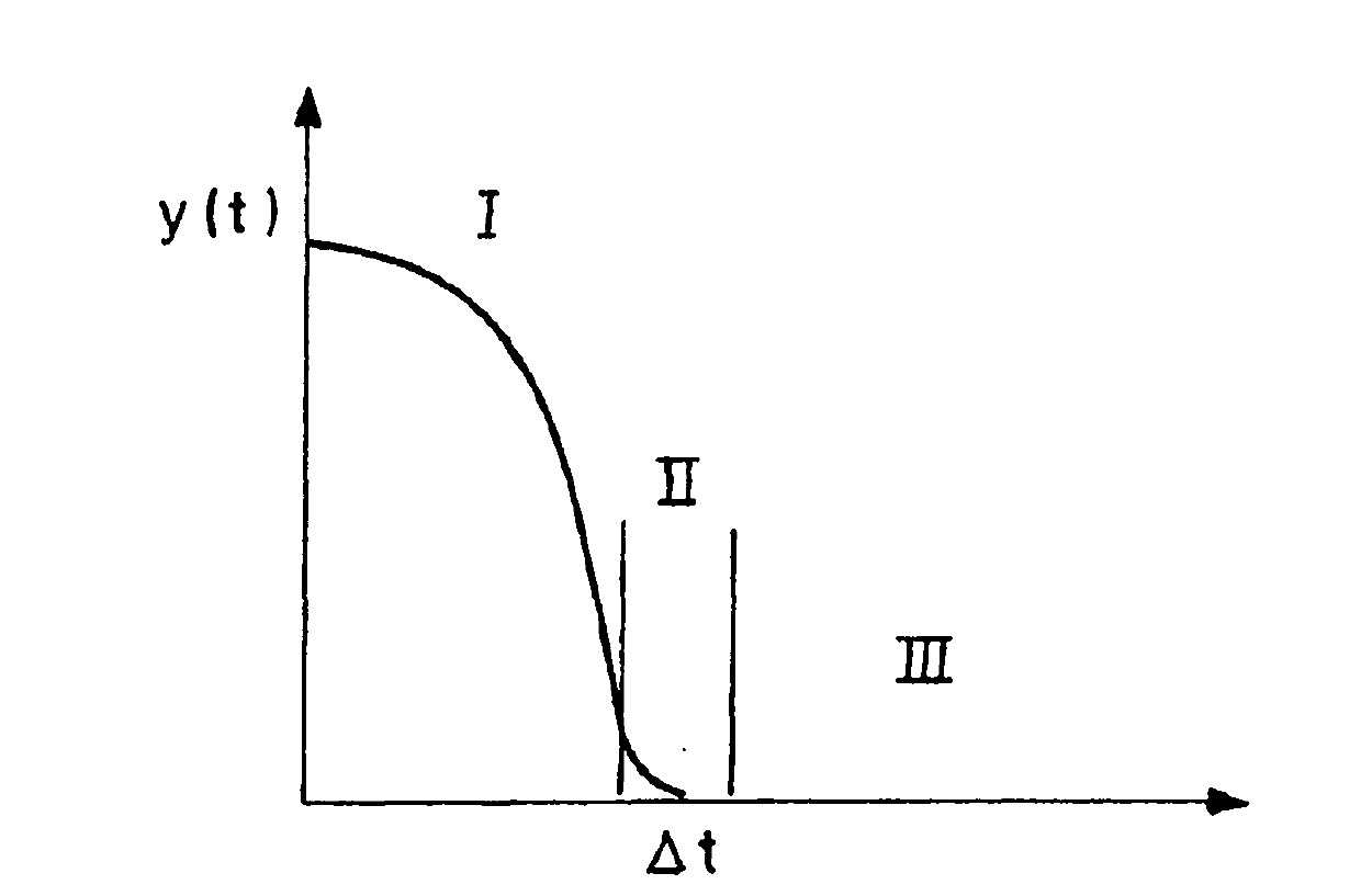
[0032] figure 1 A point on the tread of a vehicle tire is shown in principle as a function of time in the y-direction through the point where it hits the road. therefore figure 1 Approximately shows the motion curve of a point on the tread. In range I the tire spins evenly, in range II the tire starts to deform and hits the road and in range III the tire touches the road.

[0033] It can be deduced by suitable approximate calculation that the acceleration value (the piezoelectric element bears the acceleration value in the range II) and 1 / (Δt) 2 Proportional ([Delta]t gives the time interval in which the tire tread deforms and thus changes the direction of motion of the fibers). Depending on the properties and elasticity of the tire and the angular velocity depending on the vehicle speed, this time interval Δt can be made extremely short, resulting in accelerations of the order of 10,000 grams.

[0034] Additional influences due to road flatness or other driving dynamics f...


PUM


Abstract

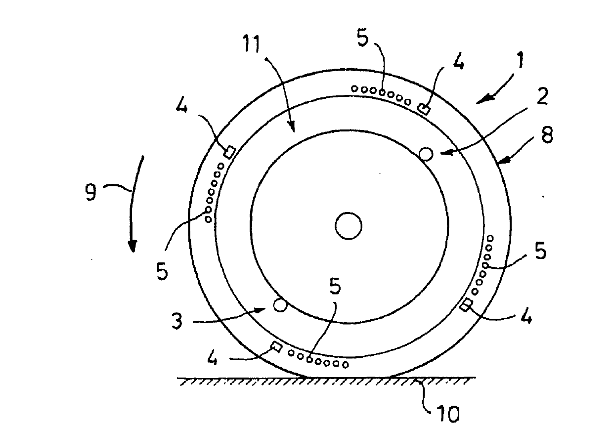
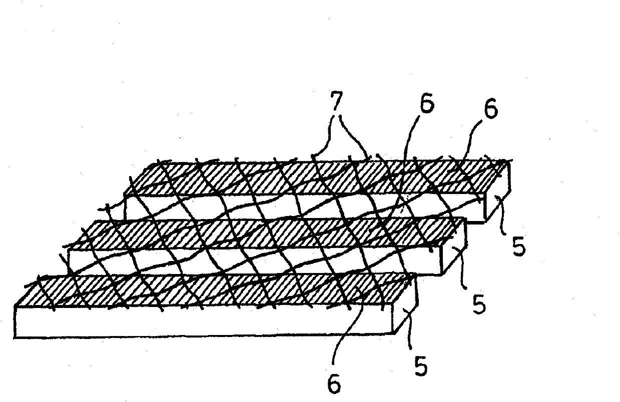
The invention relates to a device for generating electrical energy in a rotating system (1) for supplying electronic components (2, 3) in the system with current, with external forces which act on the system and which act on piezoelectrically active energy converters in the system, as a result of which electrical energy is generated, and with an electronic system (4) for processing the generated electrical energy and passing it onto the components (2, 3). In order for the rotational characteristics of the system to be influenced as little as possible, while permitting said system to provide a large amount of energy, to function reliably and have a long service life even under extreme acceleration conditions, the invention proposes that the piezoelectrically active energy converters are piezoceramic fibres (5), each of which has an electrode (6), and the electrode (6) of the fibres which generate a charge of the same polarity are connected via an electrically conductive external electrode (7).

Description

technical field [0001] The invention relates to a device for generating electrical energy in a rotating system, for supplying electrical components in the system with current, with an external force acting on the system, said external force acting on a piezoelectrically activated energy converter in the system , thereby generating electrical energy, and having circuitry for processing the generated electrical energy and conducting the electrical energy to the element. Background technique [0002] Such a device is known from DE 603 ​​10 104 T2. A piezoelectric element and a steering mass and a control circuit for contacting the piezoelectric element, which are electrically connected to the piezoelectric element, are arranged here inside the tire or pneumatic tire. The steering mass serves to deflect the piezo elements as a result of external forces, which in use act on the steering mass for generating an electrical charge. This charge or electrical energy is made available...

Claims


Application Information

Patent Timeline
Patent Type & Authority Applications(China)
IPC IPC(8): B60C23/04
CPCH02N2/18B60C23/041
Inventor H-J·施赖纳R·宾迪希K·辰特克A·克尔恩贝格尔
Owner CERAMTEC
Learn More