Method for determining dead zone of valve

A dead zone, control valve technology, applied in drilling equipment and methods, earthwork drilling, automatic control systems for drilling, etc., can solve problems such as changes and infeasibility, and achieve the effect of eliminating dead zones

Inactive Publication Date: 2011-04-20
SANDVIK MINING & CONSTR OY
View PDF5 Cites 5 Cited by
  • Summary
  • Abstract
  • Description
  • Claims
  • Application Information

AI Technical Summary

Problems solved by technology

[0005] But this is not feasible in practice, the reason is that the dead zone varies according to the valve

Method used


Image

  • Method for determining dead zone of valve
  • Method for determining dead zone of valve
  • Method for determining dead zone of valve

Examples


Embodiment Construction

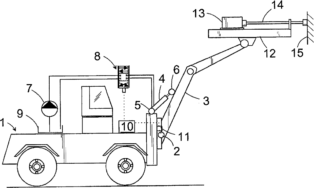
[0025] figure 1 An actuator in a rock drilling rig is schematically shown. Reference numeral 1 schematically denotes a base to which a drill arm 3 is rotatably connected via a joint 2 . The drill arm 3 is rotatable about the axis of the joint 2 by means of an actuator (i.e. a hydraulic cylinder 4), one end of which is connected to the base 1 by means of a joint 5 and the other end is correspondingly rotatably connected to the drill arm by means of a joint 6 3. To control the hydraulic cylinder 4 , pressure medium from the pump 7 can be fed to the hydraulic cylinder via a proportional control valve 8 , whereby pressurized fluid also flows from the other end of the hydraulic cylinder 4 into a pressurized fluid container 9 via the valve 8 . To control the hydraulic cylinder 4, a proportional control valve is controlled by a control unit 10, to which a sensor 11 representing the angle of rotation of the boom is also connected. Additionally, the figures show a feed beam 12 at th...


PUM


Abstract

The invention relates to a method for determining the dead zone of a proportional control valve (8) used for controlling an actuator of a rock drilling device, the method comprising controlling the control valve (8) with an electric P controller (12) and measuring the position of the actuator in a coordinate system representing its movement with a separate position detector. The dead zone is determined by means of a product of the P controller of the control valve (8) and the difference value.

Description

technical field [0001] The invention relates to a method for determining the dead zone of a proportional control valve for controlling an actuator of rock drilling equipment, said method comprising controlling the control valve with an electronic P controller and using a separate position The detector measures the position of the actuator in a coordinate system representing its movement. Background technique [0002] In hydraulic rock drilling equipment, the actuators for the feed beam cylinders of the drilling boom are controlled by using proportional directional control valves. In practice, this involves controlling the actuator in both directions, whereby the actuator does not move when the valve is in the middle position, i.e. at 0 position, and when the spool is displaced in either direction the actuator moves relative to The deflection of the spool moves at a proportional speed such that the more the spool deviates from the zero position, the faster the actuator will ...

Claims


Application Information

Patent Timeline
Patent Type & Authority Applications(China)
IPC IPC(8): E21B7/02E21B44/00F15B13/044F15B19/00
CPCF15B19/002E21B7/022E21B44/00F15B13/044
Inventor 尤西·普拉马库斯·塞雷莱
Owner SANDVIK MINING & CONSTR OY
Why Eureka
Try Eureka