Mixing device for regulating density of drilling liquid

A drilling fluid density and mixing device technology, applied in mixers, mixing methods, fluid mixers, etc., can solve the problems of poor mixing effect of static mixers, easy formation of natural gas hydrates, and stratification of mixed drilling fluids. Good mixing effect, particle size reduction, long service life effect

Active Publication Date: 2011-04-27
CHINA NAT OFFSHORE OIL CORP +1
View PDF5 Cites 12 Cited by
  • Summary
  • Abstract
  • Description
  • Claims
  • Application Information

AI Technical Summary

Problems solved by technology

At present, the underbalanced drilling technology is also developing rapidly. The underbalanced drilling technology uses the drilling fluid pressure slightly lower than the formation pressure to reduce the damage to the formation, improve the drilling speed and reduce the lost circulation in depleted oil reservoirs; When drilling in some areas, the following problems are also faced: poor stability of shale, large amount of drilling fluid, difficulty in borehole cleaning, shallow gas and shallow water flow, low temperature and high pressure environment on the seabed, easy formation of natural gas hydrate, low temperature drilling Fluid rheology, narrow window between formation pressure and fracture pressure, etc.
The general static mixer has the advantages of small flow resistance and high reliability, but due to the limitation of the size of the mixer, the mixing effect of the static mixer is poor, especially for non-Newtonian fluids with high viscosity and components with different viscosities and surface tensions , the mixing resistance increases sharply, and it is difficult to form the required turbulence
In the field of oil drilling, static mixers may cause serious problems such as stratification of mixed drilling fluids, so a dynamic mixer that can achieve better mixing effects must be used

Method used


Image

  • Mixing device for regulating density of drilling liquid
  • Mixing device for regulating density of drilling liquid
  • Mixing device for regulating density of drilling liquid

Examples


Embodiment Construction

[0017] The present invention will be described in detail below in conjunction with the accompanying drawings and embodiments.

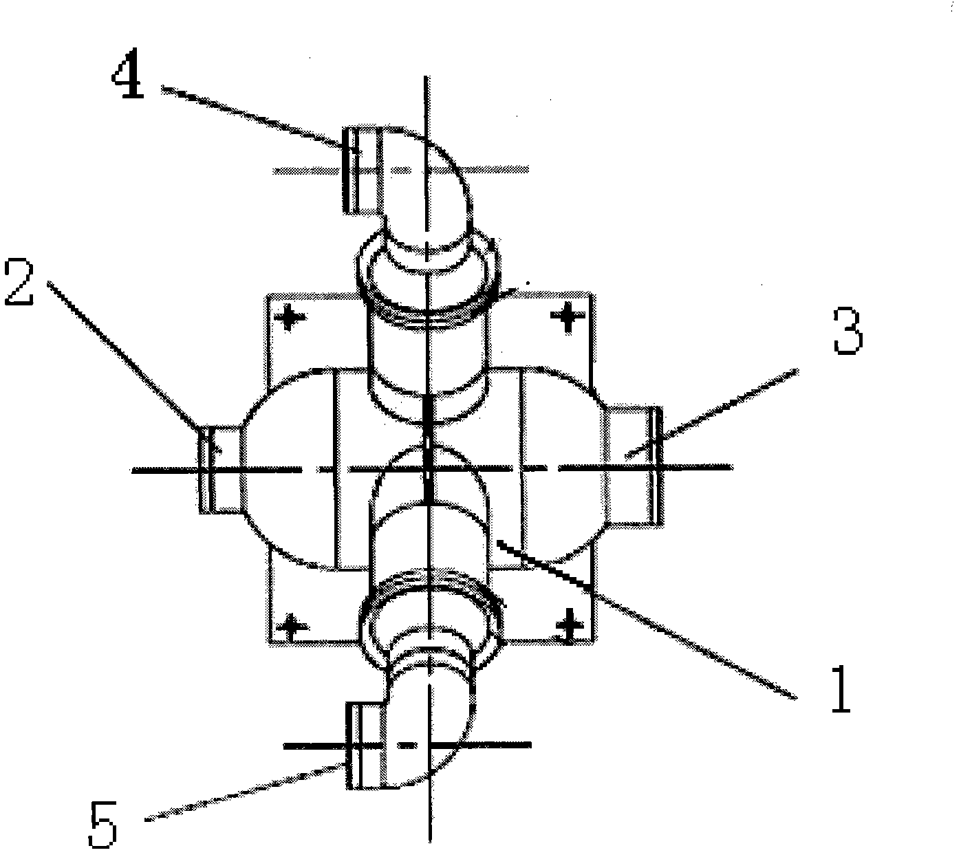
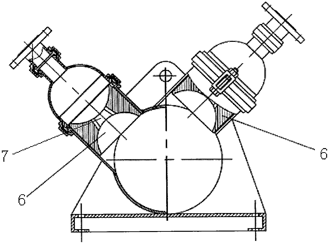
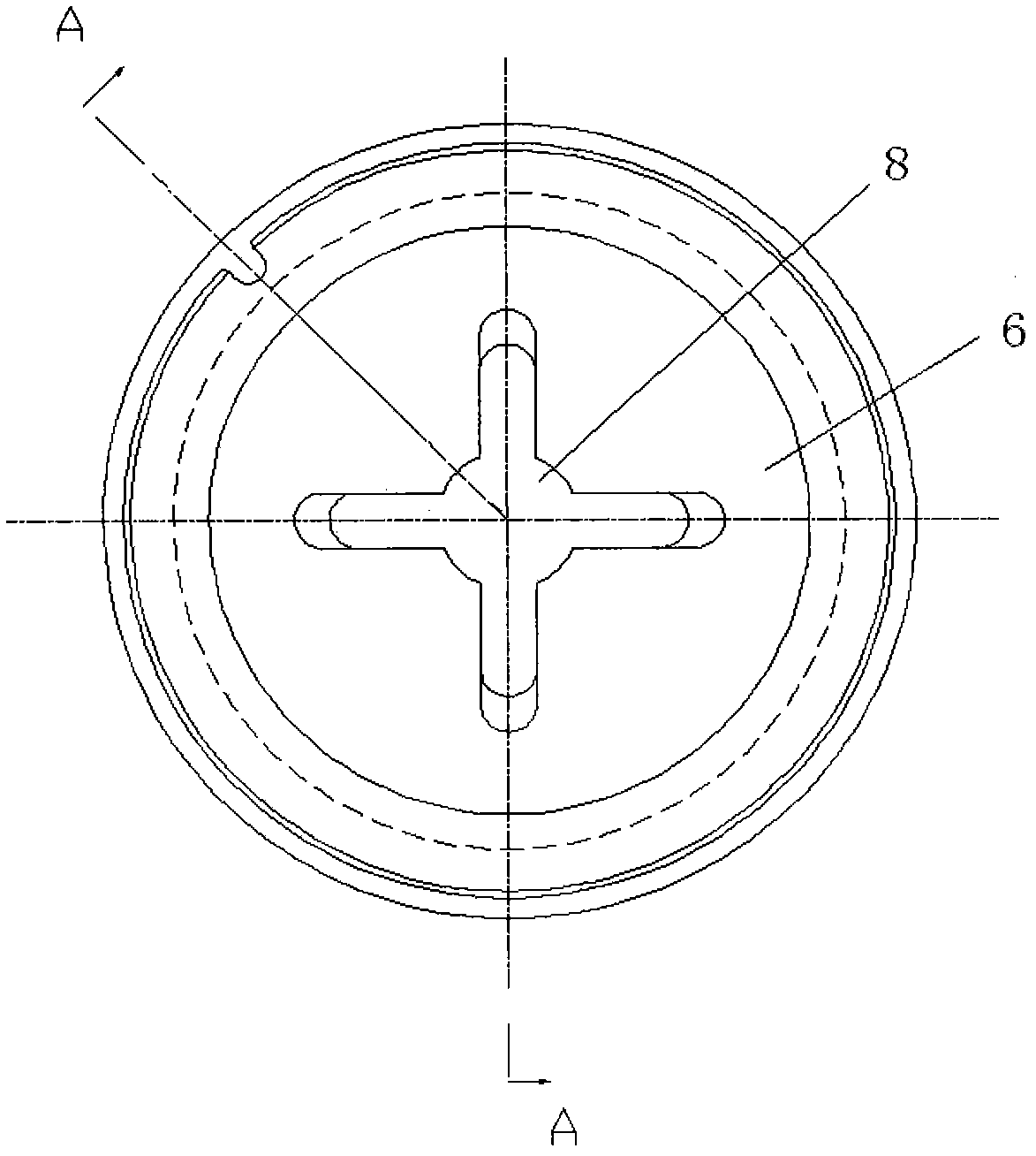
[0018] Such as figure 1 , figure 2 As shown, the present invention comprises a tubular mixing device body 1, one end of the mixing device body 1 is provided with a drilling fluid inlet 2, and the other end is provided with a mixed fluid outlet 3, and the circumference of the mixing device body 1 is provided with a high-density drilling fluid inlet 4 and a seawater inlet 5, the high-density drilling fluid inlet 4 and the seawater inlet 5 are respectively connected to the mixing device body 1 through an interface 6, and the center of each interface 6 is provided with a short throat 7, each throat Install a nozzle 8 in 7 (as image 3 , Figure 4 shown), the length of the throat can be determined as required.

[0019] In the above-mentioned embodiment, the cross-section of each nozzle 8 is in the shape of a plum blossom, and the number of plum blosso...


PUM


Abstract

The invention relates to a mixing device for regulating the density of a drilling liquid, which is characterized by comprising a tubular mixing device body, wherein one end of the mixing device body is provided with a drilling liquid inlet and the other end is provided with a mixing liquid outlet, the peripheral direction of the mixing device body is respectively connected with a high-density drilling liquid inlet and a seawater inlet through ports, the centers of the two ports are respectively provided with a nozzle with a quincuncial cross section through throats; and the axes of the two ports are mutually staggered with an angle on the cross section of the mixing device body and arranged eccentric to the exes of the mixing device body. Two groups of high-speed low-pressure fluids sprayed from the two nozzles are mutually staggered and generate shear mixing in a low-speed region of the mixing device body, thus the granularity of the mixed components is reduced and the mixed components are more uniformly mixed. The mixing device has the advantages of high density regulating speed, high regulating precision and good mixing effect, and has better mixing effect special for the mixing of high-viscosity non-Newtonian flow heavy mud and sweater/freshwater.

Description

technical field [0001] The invention relates to a mixing device, in particular to a mixing device for adjusting the density of drilling fluid. Background technique [0002] Drilling fluid balanced drilling is a mature drilling technology in the world at present. The balanced drilling technology uses the static pressure of drilling fluid to balance the bottom pressure to ensure the normal drilling. At present, the underbalanced drilling technology is also developing rapidly. The underbalanced drilling technology uses the drilling fluid pressure slightly lower than the formation pressure to reduce the damage to the formation, improve the drilling speed and reduce the lost circulation in depleted oil reservoirs; When drilling in some areas, the following problems are also faced: poor stability of shale, large amount of drilling fluid, difficulty in borehole cleaning, shallow gas and shallow water flow, low temperature and high pressure environment on the seabed, easy formation ...

Claims


Application Information

Patent Timeline
Patent Type & Authority Applications(China)
IPC IPC(8): B01F5/02B01F3/08
Inventor 李嗣贵雷宗明付英军殷志明孔松涛刘科朱荣东王堃
Owner CHINA NAT OFFSHORE OIL CORP
Why Eureka
Try Eureka