Assistive device tool for placing working tools

A technology for tooling and auxiliary tools, applied in the field of auxiliary tools for placing tooling, can solve the problems of large volume, inconvenient access, and small number of display, and achieve the effects of low cost, good durability, and easy access.

Active Publication Date: 2011-04-27
CHERY AUTOMOBILE CO LTD
View PDF7 Cites 9 Cited by
  • Summary
  • Abstract
  • Description
  • Claims
  • Application Information

AI Technical Summary

Problems solved by technology

[0006] The purpose of the present invention is to provide an auxiliary device for placing tooling, which solves the problems of the existing tooling device for placing small quantities, large volume, and inconvenient access.

Method used


Image

  • Assistive device tool for placing working tools
  • Assistive device tool for placing working tools
  • Assistive device tool for placing working tools

Examples


Embodiment 1

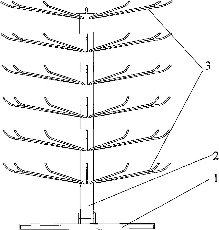
[0020] Embodiment 1, according to the principle of "in the case of the same volume, the space occupied by the ring or circle is the smallest", the present invention adopts a ring tree structure design, so that the present invention reduces the occupation of the site and frees up space for the operation of employees . Such as figure 1 , 2 As shown, an auxiliary device for placing tooling, including a base 3 and a rotating column 2, on which a plurality of hanging arms 1 for hanging tooling are arranged. The mandrel 5 is fixedly arranged on the base 3 , the mandrel 5 is movably socketed in the rotating column 2 , and the rotating column 2 can rotate relative to the base 3 .

Embodiment 2

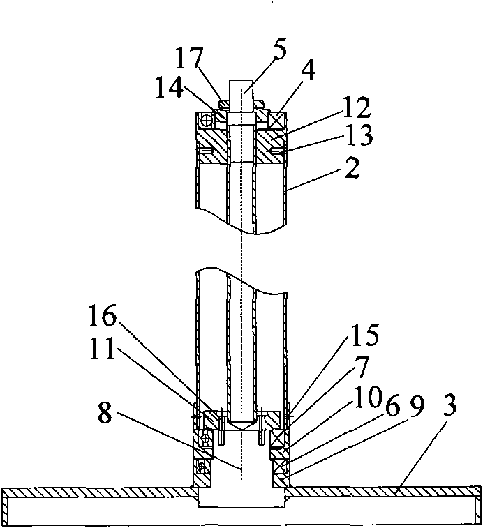
[0021] Embodiment 2, on the basis of the technical solution of Embodiment 1, in order to make the rotating column rotate smoothly and maintain the stability of the auxiliary device, the bottom end of the mandrel 5 is connected to the large shaft 8 fixed to the base, and the bottom end of the large shaft 8 is provided with a second A bearing seat 9 and an eccentric ball type first bearing 6; the second bearing seat 12 is fixed by the first screw 13 in the top end of the rotating column 2, the second bearing seat 4 is arranged in the second bearing seat 12, and the mandrel 5 is socketed Second bearing 4.

Embodiment 3

[0022] Embodiment 3, on the basis of the technical solution of Embodiment 2, in order to make the rotating column more smooth and easy to disassemble and maintain, a third bearing seat 10 and a third bearing 7 are arranged above the first bearing 6, and the third bearing The seat 10 is fixedly connected with the rotating column 2 through the second screw 15; the bottom end of the mandrel 5 is provided with a large end cap 11, and is connected with the large shaft 8 through a bolt 16; the top end of the mandrel 5 is provided with a small end cap 14 and The nut 17, after the nut 17 is tightened, the small end cover 14 compresses the second bearing 4.

[0023] Both the second bearing and the third bearing are deep groove ball bearings. Described first screw, second screw adopt hexagon socket head cap screw.

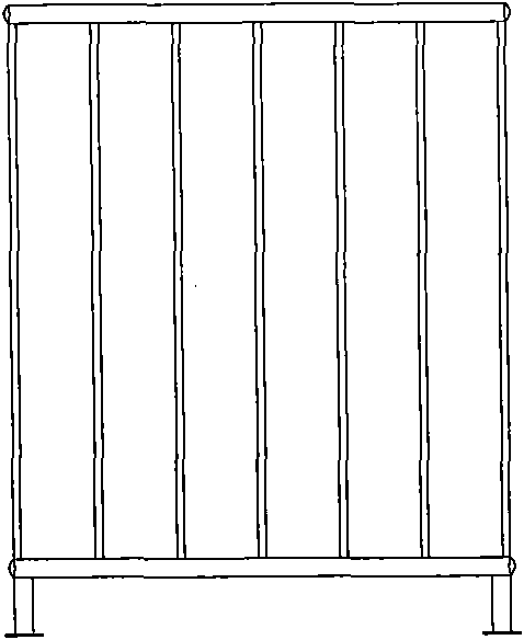
[0024] For safety, an opening safety guardrail is also provided outside the auxiliary device. Such as image 3 , 4 shown. Eliminate possible hidden dangers in the proce...


PUM


Abstract

The invention discloses an assistive device for placing working tools, comprising a base and a column spinner, wherein the column spinner is provided with a plurality of hanging arms for hanging the working tools. The assistive device is characterized in that the base is fixedly provided with a mandrel movably sheathed in the column spinner, and the column spinner can rotate relative to the base. The six layer of hanging arms for hanging the working tools are formed, wherein drilled holes on each layer are welded with twelve hanging arms. Because of the adoption of the design of the annular tree structure, more working tools are contained in a limited space. A movable swiveling mechanism is adopted, and employees easily classify the working tools and conveniently fetch the working tools when various types of vehicle are produced in a paint production line, thereby avoiding false and neglected assembly for employees. In addition, a safety guard rail is adopted, so that no potential safety hazard exists in the use process and enough safety is ensured. The assistive device is made of common materials and has the advantages of simple manufacture process, good durability and lower cost.

Description

technical field [0001] The invention relates to an appliance for placing tooling. Specifically, it relates to an auxiliary device for placing tooling on an automobile painting line. Background technique [0002] In the previous automobile painting process, the automobile painting line generally produced only one model, and the number of on-board tooling used was not too much. Generally, material boxes or simple tooling hangers can be used to solve the problem of on-site tooling placement. In the current automobile painting process, the automobile painting line generally produces more than 3 models at the same time, in order to meet the diversified needs of the market and improve the utilization rate of existing equipment. When each model is produced on the painting production line, it needs to be equipped with corresponding tooling to avoid damage to the painted parts and improve the quality of body painting. Different models are equipped with different tooling, some are s...

Claims


Application Information

Patent Timeline
Patent Type & Authority Applications(China)
IPC IPC(8): B25H3/04
Inventor 徐国庆张安扩孙小忠潘赟赟
Owner CHERY AUTOMOBILE CO LTD
Why Eureka
Try Eureka