Loading and unloading transport vehicle
A technology for loading and unloading trucks and lifting rods, applied in the direction of lifting devices, etc., can solve problems such as low work efficiency, occupying space, and breakage of release film rolls, and achieve the effect of simple and simple structure, small overall volume, and firm clamping.
- Summary
- Abstract
- Description
- Claims
- Application Information
AI Technical Summary
Problems solved by technology
Method used
Image
Examples
Embodiment 1
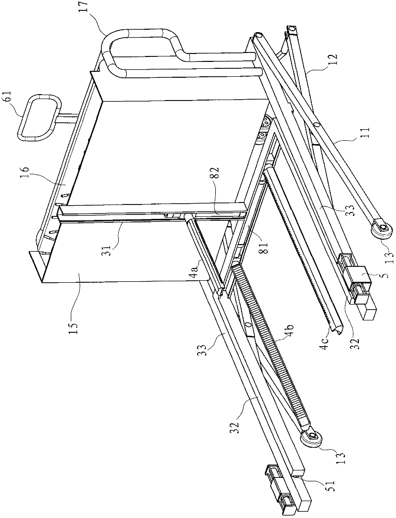
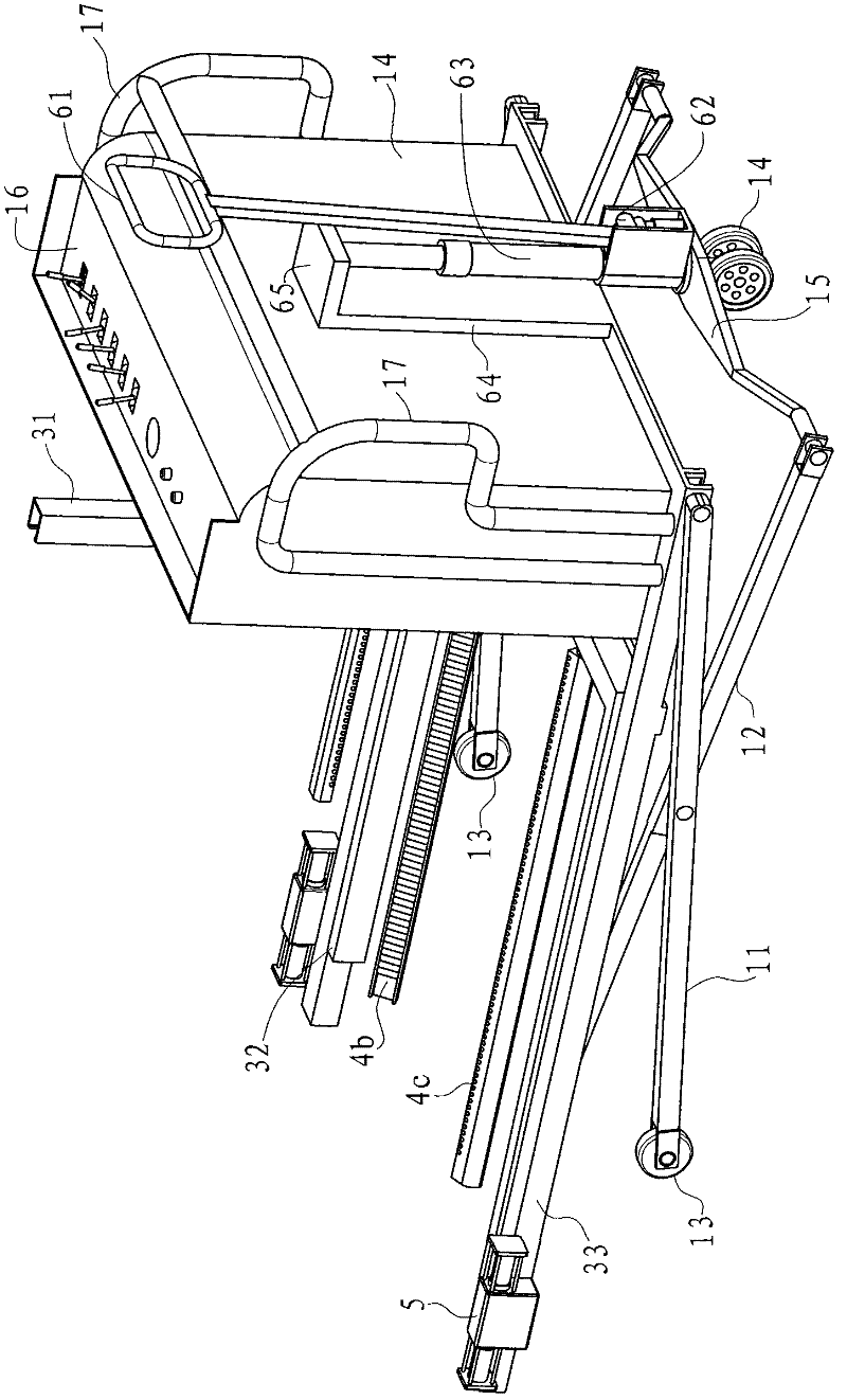
[0043] Example 1, such as figure 1 with figure 2 As shown, the handling truck in this embodiment includes a first lifting rod 11, a second lifting rod 12, a clamping mechanism, a driving mechanism and a controller. There are two first elevating rods 11, which are arranged on the left and right sides. Each first elevating rod 11 front end is provided with a front guide wheel 13, and the second elevating rod 12 is also two, respectively corresponding to the first elevating rod 11 middle part. hinged to each other, see Figure 5 As shown, each second elevating rod 12 has a roller 121 at the front end, and a connecting portion 15 is connected between the rear ends of the two second elevating rods 12. The bottom end of the connecting portion 15 is provided with a rear guide wheel 14 for driving The mechanism is arranged on the connecting portion 15 for driving the clamping mechanism to lift up and down, and the controller has a first control output terminal connected to the driv...
Embodiment 2
[0051] Example 2, such as Figure 11 and Figure 12 As shown, the channel bracket 31 in this embodiment includes three three sub-channel frames that intersect at one point, and the angle formed between adjacent sub-channel frames is 120°, and the three clamping rods are It can be movably arranged on the respective sub-guiding trough frames.
[0052] The driving source in this embodiment is a motor 7, the motor 7 can be reversed, the motor 7 has a tapered output gear 71, and each clamping rod bottom part is provided with a slider 42, and the slider 42 has an internal screw hole , the motor 7 is in transmission connection with each clamping rod through a transmission mechanism, the transmission mechanism includes three screw rods 43 respectively matched with the slider 42 and three bevel input gears 44 meshing with the bevel output gear 71, each The screw rods 43 are all rotatably arranged in the guide groove bracket 31 , and each conical input gear 44 is arranged at the end o...
Embodiment 3
[0053] Example 3, such as Figure 13 As shown, the driving source in this embodiment is a motor 83 and a motor 84, the guide groove bracket 31 is T-shaped, and a slider 42 is respectively provided at the bottom of each clamping rod. The slider 42 has an inner screw hole, and each slider Block 42 is connected with motor drive by respective screw rod 43, and screw rod 43 and motor are all arranged in the guide groove support 313, certainly, if motor is bigger, also can be located at the guide groove support 31 back, wherein the first clamping bar 4a passes through The motor 82 is used to drive, and the second clamping rod 4b and the third clamping rod 4c below are driven by the same motor 81 . Other structures and handling operation process can refer to embodiment 1.
PUM
 Abstract
Description
Claims
Application Information
 - R&D
- Intellectual Property
- Life Sciences
- Materials
- Tech Scout
- Unparalleled Data Quality
- Higher Quality Content
- 60% Fewer Hallucinations
Browse by: Latest US Patents, China's latest patents, Technical Efficacy Thesaurus, Application Domain, Technology Topic, Popular Technical Reports.
© 2025 PatSnap. All rights reserved.Legal|Privacy policy|Modern Slavery Act Transparency Statement|Sitemap|About US| Contact US: help@patsnap.com


