Bending machine for spiral light tube

A technology of bending machine and lamp tube, applied in glass reshaping, glass manufacturing equipment, glass molding, etc., can solve the problems of high production cost, unstable shape, low efficiency and other problems of exposed tube manufacturers, and achieve product shape The effect of stability, high pass rate and simple operation

Inactive Publication Date: 2011-04-27
宋云峰
View PDF4 Cites 33 Cited by
  • Summary
  • Abstract
  • Description
  • Claims
  • Application Information

AI Technical Summary

Problems solved by technology

[0002] At present, the bending process of the spiral exposed tube is manual, that is, the operator holds the lamp tube and heats it on the flame and then bends it into the desired shape by hand. Only one leg can be bent at a time, which is inefficient and unstable in shape. It takes a long time for operators to learn this technology, and the production cost of exposed pipe manufacturers is high

Method used


Image

  • Bending machine for spiral light tube
  • Bending machine for spiral light tube
  • Bending machine for spiral light tube

Examples


Embodiment Construction

[0012] The following best examples of the spiral lamp tube bending machine of the present invention do not limit the protection scope of the present invention.

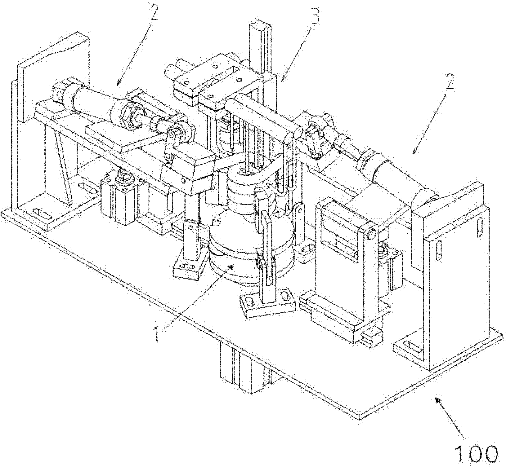
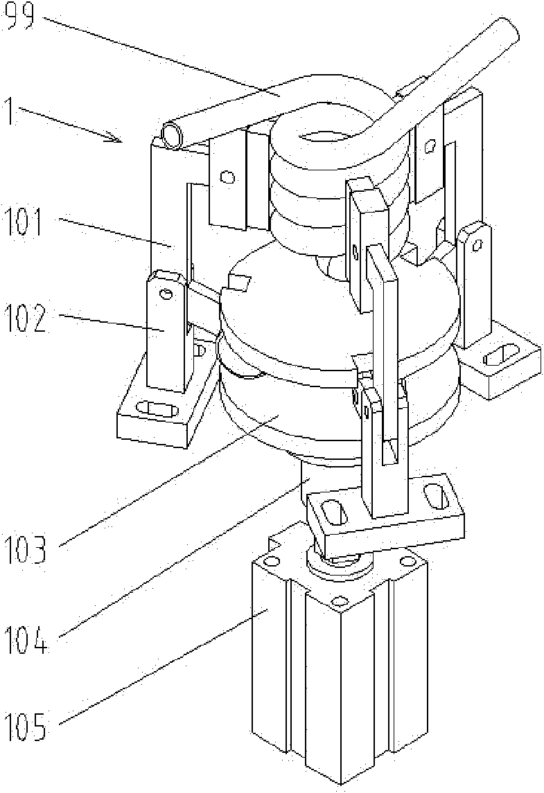
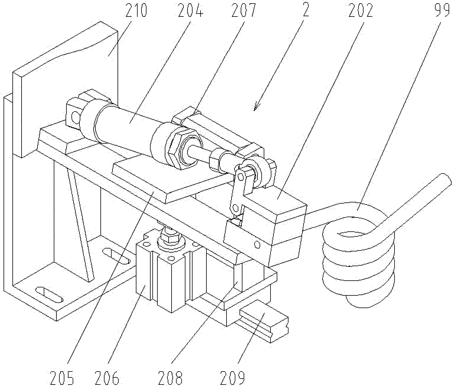
[0013] refer to figure 1 , figure 2 , image 3 , Figure 4 , Figure 5 , provides a spiral lamp tube bending machine, including a frame 100, and also includes a lamp tube clamping mechanism 1 installed on the frame 100, and two sides of the lamp tube clamping mechanism 1 are respectively provided with a bending pin to execute A flame heating system 3 is arranged above the mechanism 2 and the lamp clamping mechanism 1 .

[0014] The lamp clamping mechanism 1 is arranged in the middle of the frame 100, and includes a drive cylinder 105 installed on the frame 100, a push plate 103 rotatably connected with the drive cylinder 105, and a linear bearing is installed on the shaft of the push plate 103. 104. There are three jaws 101 distributed at an angle of 120 degrees in the circumferential direction of the push plate...


PUM


Abstract

The invention discloses a bending machine for a spiral light tube. The bending machine comprises a frame, a light tube clamping mechanism arranged on the frame, bending actuating mechanisms which are respectively arranged at two sides of the light tube clamping mechanism, a flame heating system arranged above the light tube clamping mechanism, and an automatic control system arranged in a distribution box outside the frame, wherein, the light tube clamping mechanism is used for fixing the current spiral light tubes of all specifications; the bending actuating mechanisms are positioned at the two sides of the light tube clamping mechanism and are used for clamping two pins and executing predetermined actions; the flame heating system is arranged above the light tube and is used for heating the designated positions of the pins and can slide up and down; and the automatic control system can carry out preset control on all the actions of the frame, and the main functional element of the automatic control system is a PLC (programmable logic controller). The bending machine has the advantages of single station, small volume, low cost and high production efficiency up to over twice as high as that in the case of manual operation, and is simple in operation.

Description

technical field [0001] The invention relates to a spiral lamp tube bending machine, which is used in the processing procedure of the spiral energy-saving lamp bright tube, and bends the straight leg of the formed spiral bright tube into a shape perpendicular to the spiral body. Background technique [0002] At present, the bending process of the spiral exposed tube is manual, that is, the operator holds the lamp tube and heats it on the flame and then bends it into the desired shape by hand. Only one leg can be bent at a time, which is inefficient and unstable in shape. The period for operators to learn this technology is long, and the production cost of exposed pipe manufacturers is high. Contents of the invention [0003] The object of the present invention is to overcome the above-mentioned defects in the prior art, and provide a spiral lamp tube bending machine to replace manual bending. [0004] In order to achieve the above object, the technical solution provided by...

Claims


Application Information

Patent Timeline
Patent Type & Authority Applications(China)
IPC IPC(8): C03B23/045C03B23/06
Inventor 宋云峰
Owner 宋云峰
Why Eureka
Try Eureka