

Electric compressor
An electric compressor and electric technology, which is applied in the direction of machines/engines, liquid fuel engines, mechanical equipment, etc., can solve problems such as hindering oil flow, falling into oil shortage, and oil level drop in the oil storage part, so as to prevent the oil level from falling , performance and reliability improvements
- Summary
- Abstract
- Description
- Claims
- Application Information
AI Technical Summary
Problems solved by technology
Method used
Image

Examples
Embodiment 1
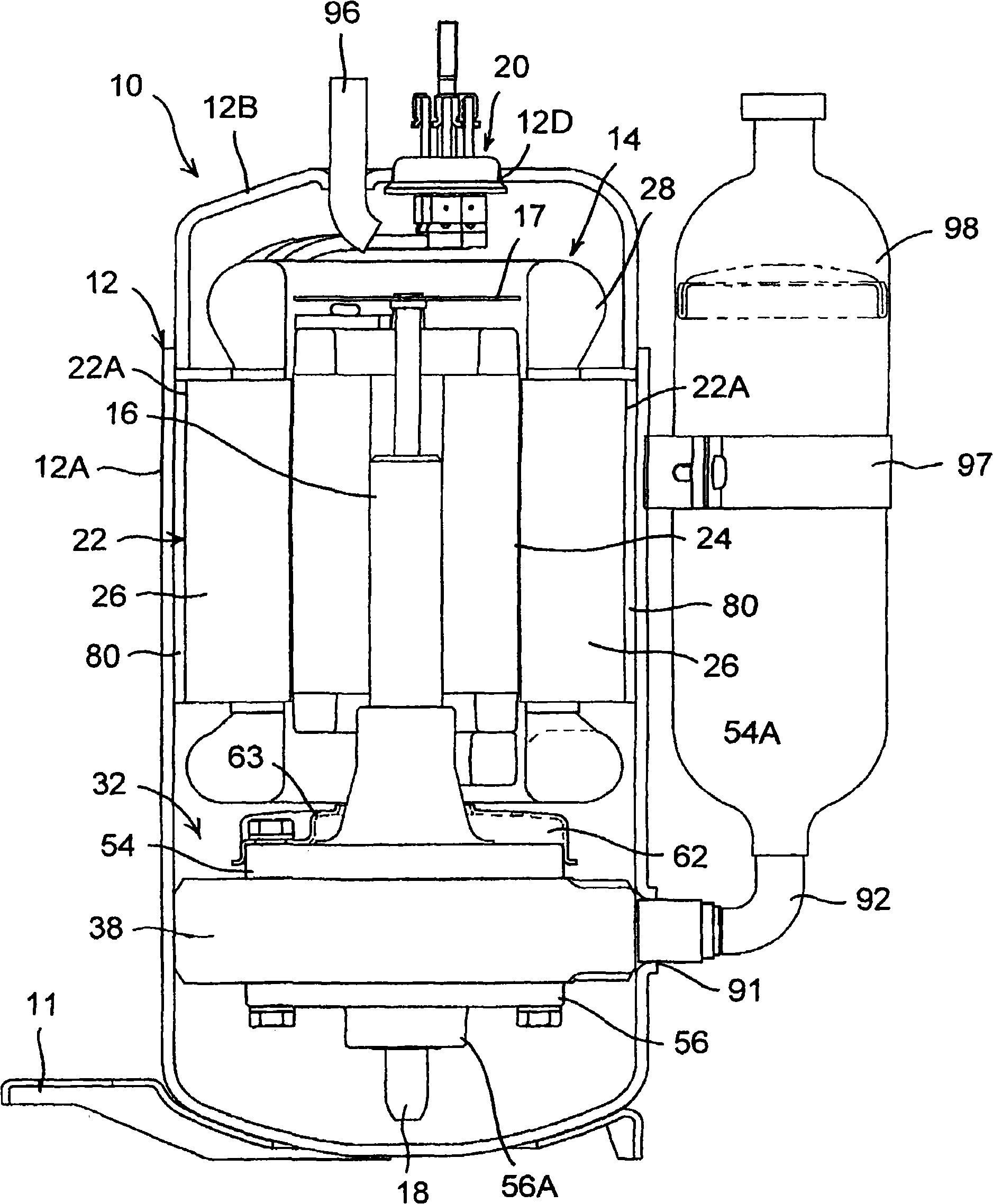
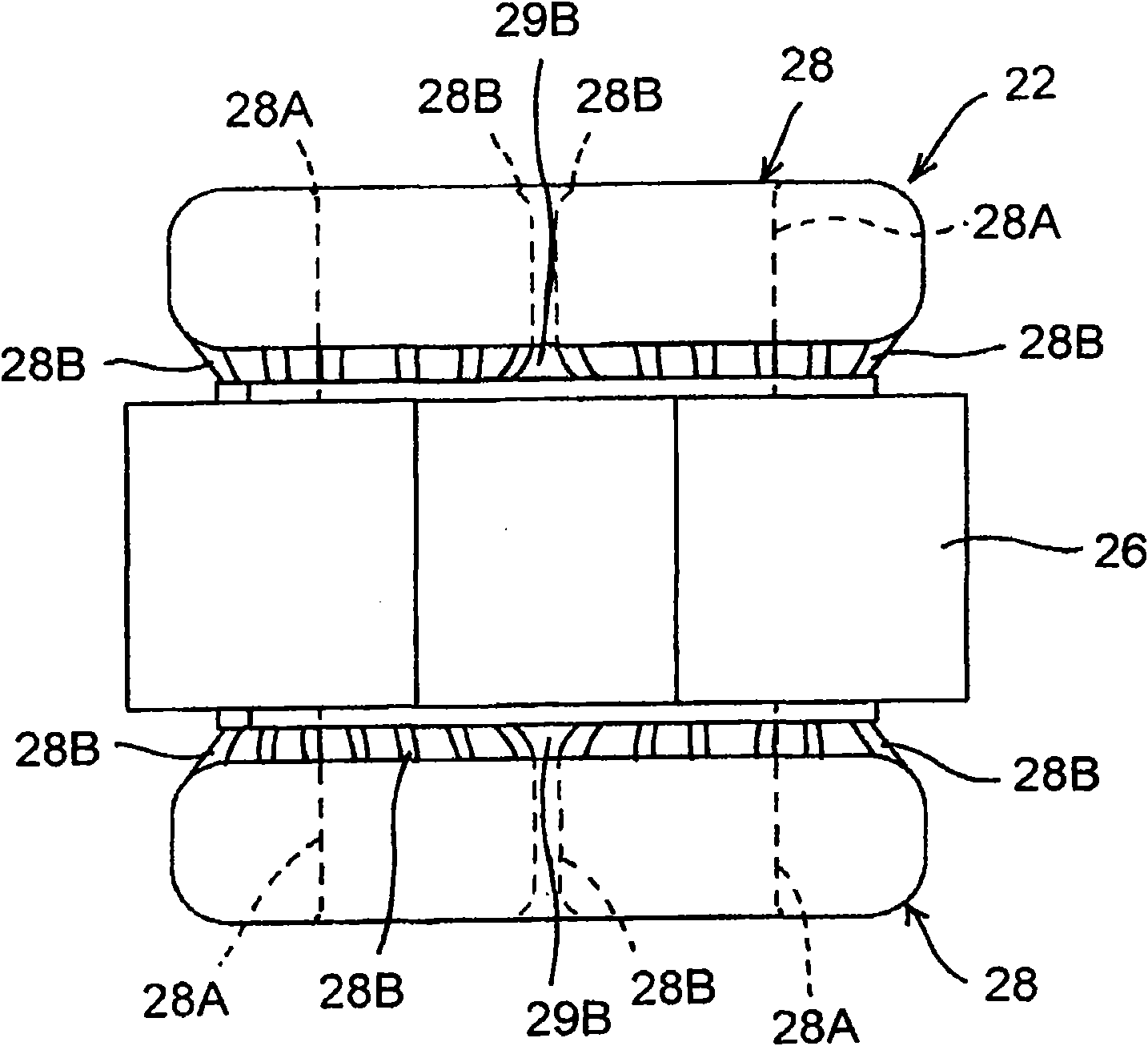
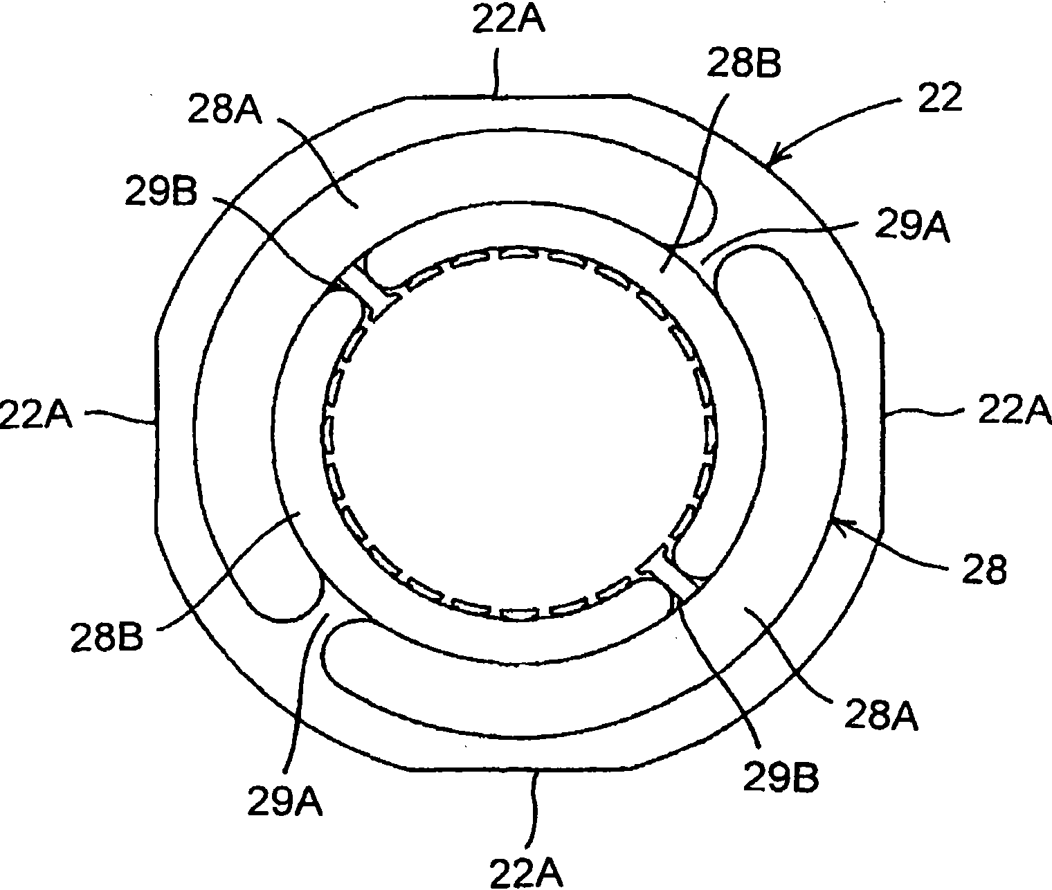
[0064] figure 1 It is a longitudinal sectional side view of a rotary compressor (electric compressor) to which an embodiment of the present invention is applied, figure 2 It is a side view of the stator of the electric element, image 3 yes figure 2 A top view of the stator. In the rotary compressor 10 of the embodiment, the electric drive element 14 and the rotary compression element 32 are housed in a vertical cylindrical airtight container 12 made of steel plates and arranged on the upper side of the inner space of the airtight container 12 . The rotary compression element 32 is arranged on the lower side of the electric element 14 and is driven by the rotating shaft 16 of the electric element 14 .
[0065] The airtight container 12 is made up of a container body 12A for accommodating the electric element 14 and the rotary compression element 32, and a substantially bowl-shaped end cap (cover body) 12B that closes the upper opening of the container body 12A. Accumula...
PUM
 Abstract
Description
Claims
Application Information