Power supply system for graded power-up

A power supply system and circuit technology, applied in battery circuit devices, high-efficiency power electronic conversion, collectors, etc., can solve problems such as increased power consumption, increased circuit cost, and unsolvable problems, so as to improve performance and reliability, and save circuit costs , the effect of improving reliability

Active Publication Date: 2021-01-08
扬州船用电子仪器研究所
View PDF3 Cites 0 Cited by
  • Summary
  • Abstract
  • Description
  • Claims
  • Application Information

AI Technical Summary

Problems solved by technology

for figure 1 In the power system shown, if only the PFC circuit is added to the main circuit, the power factor correction effect will be greatly reduced due to the existence of the auxiliary circuit, and if the PFC circuit is added to the main circuit and the auxiliary circuit at the same time (such as figure 2 shown), which will greatly increase the cost of the circuit
For the second shortcoming, it is usually to add an auxiliary power supply as a backup (such as figure 2 As shown), when one of them fails, the other power supply is automatically connected to work to ensure the normal operation of the auxiliary circuit. However, the problem of additional power consumption still cannot be solved, and the circuit cost also increases accordingly
[0005] (1) The power supply system with hierarchical

Method used


Image

  • Power supply system for graded power-up
  • Power supply system for graded power-up
  • Power supply system for graded power-up

Examples


Embodiment Construction

[0035] The present invention will be described in detail below with reference to the accompanying drawings and examples.

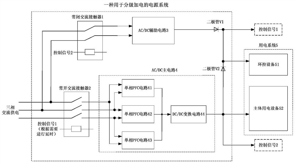
[0036] A power system for staged power-up, such as image 3 As shown, it includes normally closed AC contactor 1 , normally open AC contactor 2 , AC / DC auxiliary circuit 3 , AC / DC main circuit 4 and power system 5 . The input end of the normally closed AC contactor 1 is connected to the AC input, the output end of the normally closed AC contactor 1 is connected to the input end of the AC / DC auxiliary circuit 3, and the output end of the AC / DC auxiliary circuit 3 is connected to the The anode of the first isolation diode V1 is connected; the input end of the normally open AC contactor 2 is connected to the AC input, and the output end of the normally open AC contactor 2 is connected to the input end of the AC / DC main circuit 4, AC / DC The output end of the main circuit 4 is connected to the anode of the second isolation diode V2, the control end of the norm...


PUM


Abstract

The invention discloses a power supply system for graded power-up. The power supply system mainly comprises a normally-closed alternating current contactor, a normally-open alternating current contactor, an AC/DC auxiliary circuit, an AC/DC main circuit and an isolation diode. After normal power supply, the normally-closed alternating current contactor controls the AC/DC auxiliary circuit to be started preferentially, and environment control equipment and the like are powered up in advance. After reasonable time delay, the normally-open alternating current contactor controls the AC/DC main circuit to be started to supply power to main electric equipment. After the output of the AC/DC main circuit is stable, the AC/DC auxiliary circuit is controlled to be closed, and only the main circuit works. The AC/DC auxiliary circuit only works in the power-on initial stage, so that the problem of extra power consumption caused by continuous work of the auxiliary circuit is completely solved, andmeanwhile, the reliability of the power supply is also greatly improved. Besides, only the AC/DC main circuit is left to work after the power supply is started, so that current harmonics can be effectively reduced only by adding the PFC circuit into the main circuit, the power factor of the whole power supply is improved, and the cost is saved while the power supply performance is improved.

Description

technical field [0001] The invention belongs to the technical field of power electronics, in particular to a power supply system for hierarchical power-on. Background technique [0002] At present, in order to monitor and control the system environment, large-scale industrial, living, and medical power systems usually add some environmental control equipment. Environmental control equipment needs to realize the status monitoring, control and protection, and fault alarm functions of the system environment before the main electrical equipment is powered on. Therefore, the environmental control equipment needs to be powered on first, that is, the power system is required to have the function of hierarchical power-on. In order to achieve hierarchical power-on, the power system generally follows the figure 1 The principle shown is designed. From figure 1 It can be seen that the power supply system is divided into two parts, one part is the main circuit, which is used to supply...

Claims


Application Information

Patent Timeline
IPC IPC(8): H02M1/00H02M1/42H02J7/34
CPCH02M1/00H02M1/4208H02J7/34H02M1/0032H02M1/0083Y02P80/10
Inventor 路宇龚健王磊张彦毕磊
Owner 扬州船用电子仪器研究所
Why Eureka
Try Eureka