
Three-dimensional foot scanner

A scanner and foot technology, which is applied in the field of three-dimensional foot scanners, can solve problems such as time-consuming and cost, and achieve the effect of low production cost and reduction of the time required for scanning

Active Publication Date: 2011-04-27
THE HONG KONG POLYTECHNIC UNIV
View PDF4 Cites 49 Cited by
  • Summary
  • Abstract
  • Description
  • Claims
  • Application Information

AI Technical Summary

Problems solved by technology

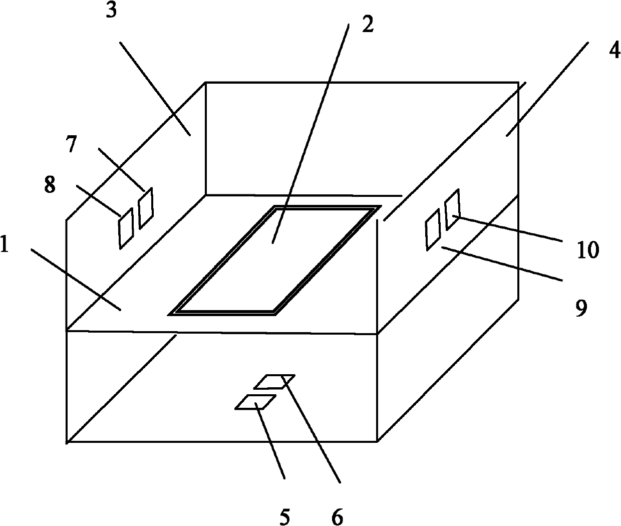
[0005] The technical problem to be solved by the present invention is to provide a three-dimensional foot scanner that uses an ordinary camera to take pictures in view of the time-consuming and high-cost defects of existing laser-based foot scanners.

Method used


Image

  • Three-dimensional foot scanner
  • Three-dimensional foot scanner
  • Three-dimensional foot scanner

Examples


Embodiment Construction

[0023] In order to make the object, technical solution and advantages of the present invention clearer, the present invention will be further described in detail below in conjunction with the accompanying drawings and embodiments.

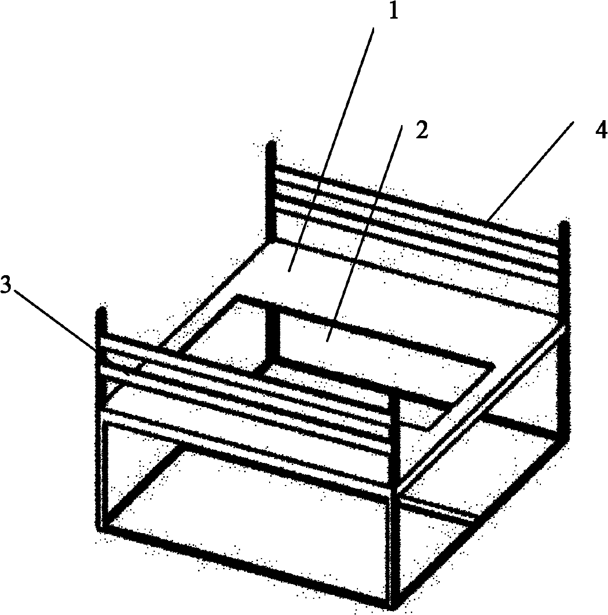
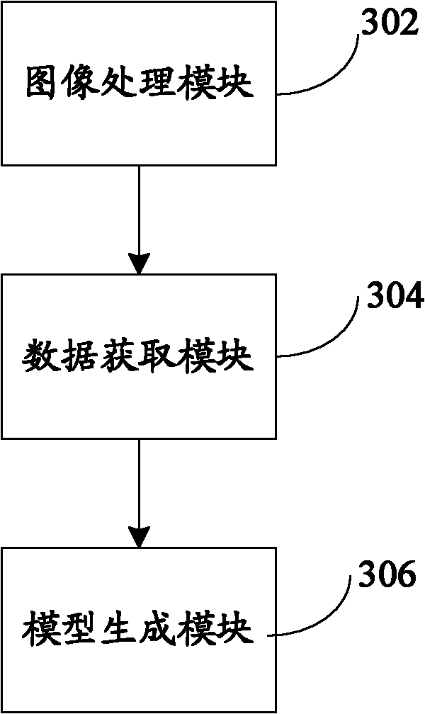
[0024] The purpose of the present invention is to reduce the cost of foot scanners and promote the development of tailor-made shoes for customers. The present invention first uses a plurality of cameras to take photos of the inner side, outer side and bottom of the foot, uses image processing methods to correct and splice the images of the captured feet, and extracts the complete inner, outer and bottom contours of the foot; The three-dimensional model of the foot can be generated by further using the contour constraint algorithm and combining the standard three-dimensional foot data.

[0025] The three-dimensional foot scanner provided by the invention includes a foot scanning device and a foot image analysis system. Wherein, the foot scanning de...


PUM


Abstract

The invention relates to a three-dimensional foot scanner which can form images or three-dimensional data records of feet of human bodies and is used for the manufacturing shoe trees. The three-dimensional foot scanner comprises a foot scanning device and a foot image analysis system, wherein the foot scanning device is used for shooting a medial border image, a lateral border image and a sole image of a foot; and the foot image analysis system is used for analyzing the medial border image, the lateral border image and the sole image of the foot so as to acquire three-dimensional foot data. In the three-dimensional foot scanner, the medial border image, the lateral border image and the sole image of the foot are shot by a plurality of cameras, the images are corrected and spliced, integrated outlines of the medial border, the lateral border and the sole of the foot are extracted, and standard three-dimensional foot data is combined so as to generate a foot three-dimensional model. By using the three-dimensional foot scanner, the scanning time and production cost are greatly reduced on the premise of ensuring certain precision.

Description

technical field [0001] The invention relates to a three-dimensional foot scanner, in particular to a three-dimensional foot scanner involving photography, which can form images or three-dimensional data records of human feet for making shoe lasts. Background technique [0002] Footwear industry is a traditional labor-intensive industry. However, with the rapid development of science and technology, especially the rapid development of computer-aided design and mechanical automation, the shoemaking industry has changed from traditional handicrafts to modern computer-aided and mechanized automatic shoemaking. Software and machines such as shoe pattern design software, shoe last design software, 3D laser scanners and automatic shoe last machines have been widely used. [0003] In the entire footwear automation design and manufacturing process, the use of foot scanners to obtain three-dimensional information of human feet is a crucial link. Only by obtaining the three-dimension...

Claims


Application Information

Patent Timeline
IPC IPC(8): G06T17/00
Inventor 艾米昇·路熙文张一帆马啸
Owner THE HONG KONG POLYTECHNIC UNIV
Learn More