Control method for digital pulse width modulation (DPWM) circuit

A digital pulse width modulation and circuit technology, applied in the electronic field, achieves the effects of good robustness, controllable delay time, and reduced system power consumption

Inactive Publication Date: 2012-11-28
NANTONG ATLANTIC MACHINERY +1
View PDF0 Cites 0 Cited by
  • Summary
  • Abstract
  • Description
  • Claims
  • Application Information

AI Technical Summary

Problems solved by technology

[0006] The problem to be solved by the present invention is: in the existing DPWM scheme, the circuit area, operating frequency and resolution are mutually restricted, and the counting comparison / delay line hybrid structure DPWM is affected by the process conditions and the working environment, which will produce unpredictable frequencies The switching noise under the environment will bring adverse effects to the system. It is necessary to optimize the DPWM circuit and design a high-resolution DPWM circuit.

Method used


Image

  • Control method for digital pulse width modulation (DPWM) circuit
  • Control method for digital pulse width modulation (DPWM) circuit
  • Control method for digital pulse width modulation (DPWM) circuit

Examples


Embodiment Construction

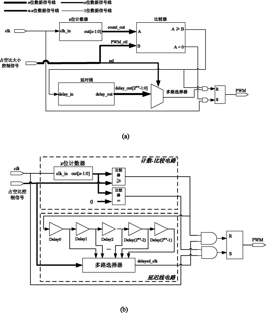
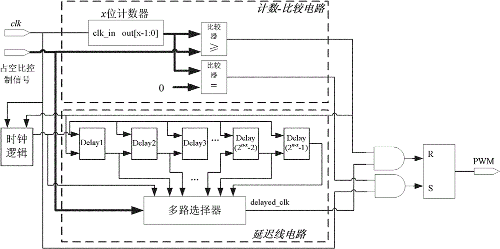
[0023] Such as figure 1 As shown, the digital pulse width modulation circuit DPWM includes a logic circuit and a logic output circuit. The logic circuit is composed of a counting-comparison circuit and a delay line circuit. The logic output circuit uses an RS latch. The present invention has carried out optimized design on this basis, as figure 2 As shown, the DPWM circuit is provided with a clock logic circuit, and the clock logic circuit provides a unified clock signal for the counting-comparison circuit and the delay line circuit. For the DPWM circuit of the n-bit duty ratio control signal, the duty ratio control signal is divided into two In the part, the high x bit input counting-comparison circuit is compared with the count value of the counter, and the low n-x bit is used as the control signal of the multiplexer to input the delay line circuit, and the delay signal output by the delay line with no delay time is selected. , where firstly the counting-comparison method ...


PUM


Abstract

The invention relates to a control method for a digital pulse width modulation circuit. By taking a counting comparison / delay line composite structure DPWM as the basis, a clock logic circuit is added, and a delay line circuit is improved; on the basis of keeping the advantages of chip area, power loss and the like in the counting comparison / delay line composite structure DPWM scheme, the processenvironment sensitivity of the circuit is optimized to obtain a high-resolution DPWM circuit, and simultaneously, the invention is slightly influenced by a manufacturing process and the working environment as much as possible, and the influence of the external environment change on the functions of the circuit is eliminated.

Description

technical field [0001] The invention belongs to the field of electronic technology, relates to the design of an integrated circuit, and is an optimized design of a digital pulse width modulation circuit DPWM, in particular a digital pulse width modulation circuit control method applied to a digitally controlled switching power supply circuit. Background technique [0002] The switching power supply using digital control technology can bring about a significant improvement in the performance of the power system, because the digital control method is flexible, less sensitive to external influences, such as being less affected by device changes, and has the ability to implement complex control algorithms . [0003] In low-power handheld devices, traditional DC-DC switching power supplies with analog pulse width modulators still occupy a relatively important position. Mainly because the digital pulse width modulator, which is the main part of the digital control loop, lacks a g...

Claims


Application Information

Patent Timeline
Patent Type & Authority Patents(China)
IPC IPC(8): H03K7/08
Inventor 常昌远王青秦建黄秋华时龙兴
Owner NANTONG ATLANTIC MACHINERY
Why Eureka
Try Eureka