Control method for digital pulse width modulation (DPWM) circuit
A technology of digital pulse width modulation and control method, which is applied in the electronic field to achieve the effects of reducing system power consumption, simple circuit structure and controllable delay time
- Summary
- Abstract
- Description
- Claims
- Application Information
AI Technical Summary
Problems solved by technology
Method used
Image
Examples
Embodiment Construction
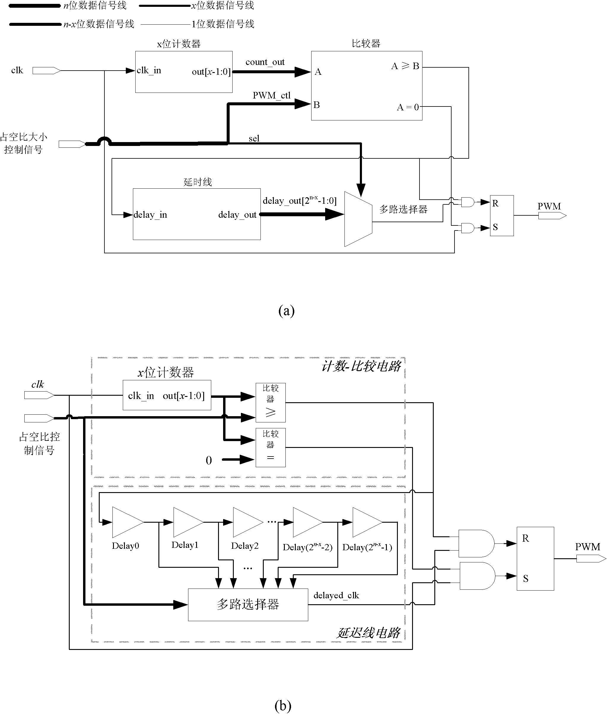
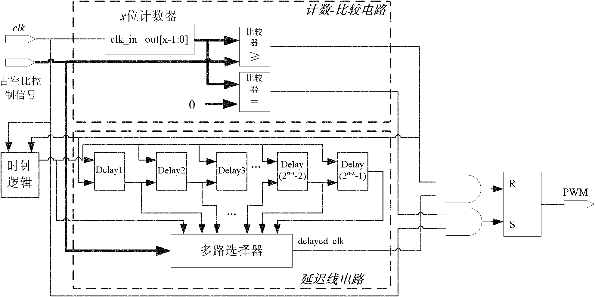
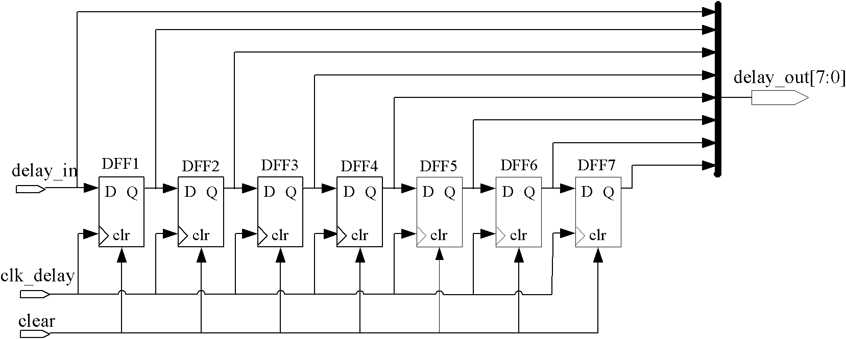
[0023] Such as figure 1 As shown, the digital pulse width modulation circuit DPWM includes a logic circuit and a logic output circuit. The logic circuit is composed of a counting-comparison circuit and a delay line circuit. The logic output circuit uses an RS latch. The present invention has carried out optimized design on this basis, as figure 2 As shown, the DPWM circuit is provided with a clock logic circuit, and the clock logic circuit provides a unified clock signal for the counting-comparison circuit and the delay line circuit. For the DPWM circuit of the n-bit duty ratio control signal, the duty ratio control signal is divided into two In the part, the high x bit input counting-comparison circuit is compared with the count value of the counter, and the low n-x bit is used as the control signal of the multiplexer to input the delay line circuit, and the delay signal output by the delay line with no delay time is selected. , where firstly the counting-comparison method ...
PUM
 Abstract
Description
Claims
Application Information
 - R&D
- Intellectual Property
- Life Sciences
- Materials
- Tech Scout
- Unparalleled Data Quality
- Higher Quality Content
- 60% Fewer Hallucinations
Browse by: Latest US Patents, China's latest patents, Technical Efficacy Thesaurus, Application Domain, Technology Topic, Popular Technical Reports.
© 2025 PatSnap. All rights reserved.Legal|Privacy policy|Modern Slavery Act Transparency Statement|Sitemap|About US| Contact US: help@patsnap.com


