Drilling method for printed circuit board (PCB)

A technology of PCB board and drilling method, which is applied in the direction of electrical components, printed circuit manufacturing, printed circuit, etc., can solve the problem of increased difficulty in the manufacture of long-edged knife drilling, increased cost of drilling tools, and decreased accuracy of drilling holes and other problems, to achieve the effect of small deformation, high drilling quality, and not easy to break the knife

Active Publication Date: 2012-11-14
DONGGUAN SHENGYI ELECTRONICS
View PDF0 Cites 0 Cited by
  • Summary
  • Abstract
  • Description
  • Claims
  • Application Information

AI Technical Summary

Problems solved by technology

At present, the drilling process of the PCB board is to use a drill to completely drill through the PCB board from one side to the other. However, when the PCB board reaches a certain thickness, the PCB board cannot be drilled due to the limitation of the length of the drill blade. through
Furthermore, when the PCB board becomes thicker, the blade length of the drill will also increase accordingly, making it more difficult to manufacture holes with long blades, resulting in an increase in the purchase cost of the drill
Further, as the length of the drill edge increases, the rigidity of the drill decreases, and under the action of the mechanical impact between the drill and the semi-finished PCB board to be processed, the deformation of the drill increases, which easily leads to a Decreased precision, increased chance of tool interruption during drilling

Method used


Image

  • Drilling method for printed circuit board (PCB)

Examples


Embodiment Construction

[0020] In order to further illustrate the technical means adopted by the present invention and its effects, the following describes in detail in conjunction with preferred embodiments of the present invention and accompanying drawings.

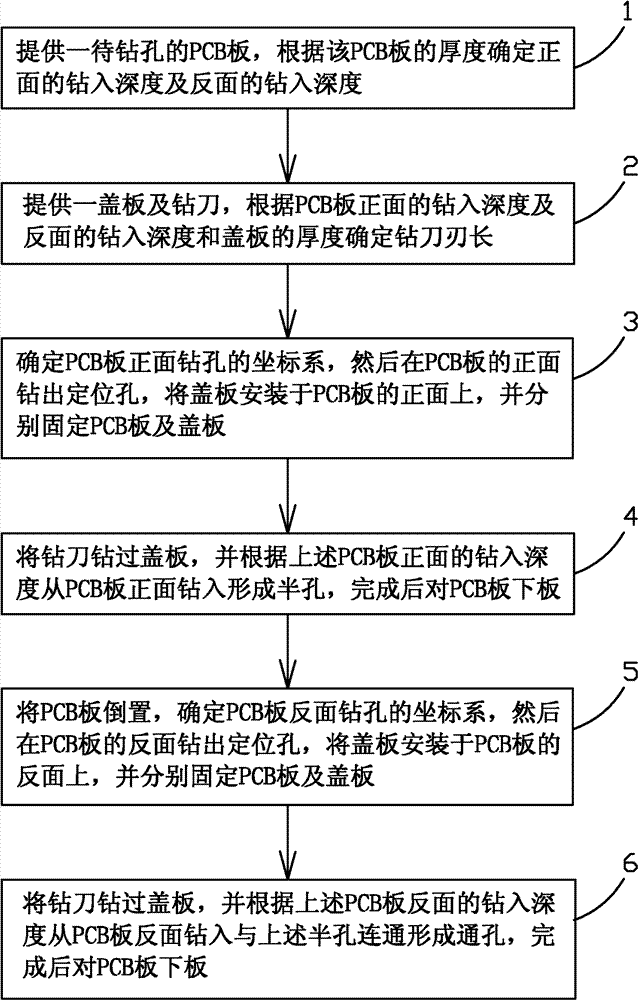
[0021] Such as figure 1 As shown, the present invention provides a kind of drilling method of PCB board, and it comprises the steps:

[0022] Step 1, provide a PCB board to be drilled, and determine the drilling depth of the front side and the drilling depth of the reverse side according to the thickness of the PCB board. In this embodiment, the drilling depth of the front side=the drilling depth of the reverse side≥ The thickness of the PCB board is ÷2+1mm. However, sometimes considering the material of the front and back sides, the drilling process, etc., under the premise of ensuring the drilling accuracy, one side can be drilled a little more, and the other side can be drilled a little less to realize the hole. connected.

[0023] Step 2...


PUM


Abstract

The invention provides a drilling method for a printed circuit board (PCB). The method comprises the following steps of: 1, providing a PCB to be drilled, and determining drilling depth of a front surface and drilling depth of a back surface according to the thickness of the PCB; 2, providing a cover plate and a drilling cutter, and determining the length of a blade of the drilling cutter according to the drilling depth of the front surface and the drilling depth of the back surface of the PCB and the thickness of the cover plate; 3, determining a coordinate system for drilling on the front surface of the PCB, drilling positioning holes on the front surface of the PCB, arranging the cover plate on the front surface of the PCB and fixing the PCB and the cover plate respectively; 4, drilling through the cover plate by using the drilling cutter, drilling from the front surface of the PCB to form a half hole according to the drilling depth of the front surface of the PCB, and then feedingthe PCB; 5, inverting the PCB, determining a coordinate system for drilling on the back surface of the PCB, drilling positioning holes on the back surface of the PCB, arranging the cover plate on theback surface of the PCB and fixing the PCB and the cover plate respectively; and 6, drilling through the cover plate by using the drilling cutter, drilling from the back surface of the PCB to be communicated with the half hole to form a through hole according to the drilling depth of the back surface of the PCB, and feeding the PCB. In the method, a short-blade long drilling cutter is used for drilling from the two ends of the front surface and the back surface of the hole respectively, so a thicker PCB can be drilled through; and the method has the advantages of lower cost, higher drilling position accuracy and difficulty in breaking the cutter.

Description

technical field [0001] The present invention relates to the technical field of printed circuit board (PCB: Printed circuit board), in particular to a method for drilling a PCB board. Background technique [0002] In the process of PCB circuit board manufacturing, it is often necessary to drill several holes with different apertures on the PCB board for component insertion or conduction. At present, the drilling process of the PCB board is to use a drill to completely drill through the PCB board from one side to the other. However, when the PCB board reaches a certain thickness, the PCB board cannot be drilled due to the limitation of the length of the drill blade. through. Furthermore, when the PCB board becomes thicker, the blade length of the drill blade will also increase accordingly, making it more difficult to manufacture holes with long blade blades, resulting in an increase in the purchase cost of the drill blade. Furthermore, as the length of the drill edge increas...

Claims


Application Information

Patent Timeline
Patent Type & Authority Patents(China)
IPC IPC(8): H05K3/00B23B35/00
Inventor 唐海波杜红兵纪成光
Owner DONGGUAN SHENGYI ELECTRONICS
Why Eureka
Try Eureka