
Automatic wiring structure for wire coiler

A technology of automatic wiring and wire reel, which is applied in the direction of using reel/photosensitive drum arrangement, cable arrangement between relative moving parts, cable installation, etc., which can solve the problem of power cord winding and slipping to other positions , can not be pulled out and other problems to achieve the effect of avoiding entanglement and improving satisfaction

Inactive Publication Date: 2011-05-04
LG ELECTRONICS (TIANJIN) APPLIANCES CO LTD
View PDF0 Cites 0 Cited by
  • Summary
  • Abstract
  • Description
  • Claims
  • Application Information

AI Technical Summary

Problems solved by technology

[0009] However, in the process of rewinding the wire reel in the prior art, the power cord often winds too much at one position, and then slides to other positions, causing the power cord to rub against the body and not return the wire. Or the power cord is tangled and knotted when pulling the cord, and cannot be pulled out, which affects the normal use of consumers

Method used


Image

  • Automatic wiring structure for wire coiler
  • Automatic wiring structure for wire coiler
  • Automatic wiring structure for wire coiler

Examples


Embodiment Construction

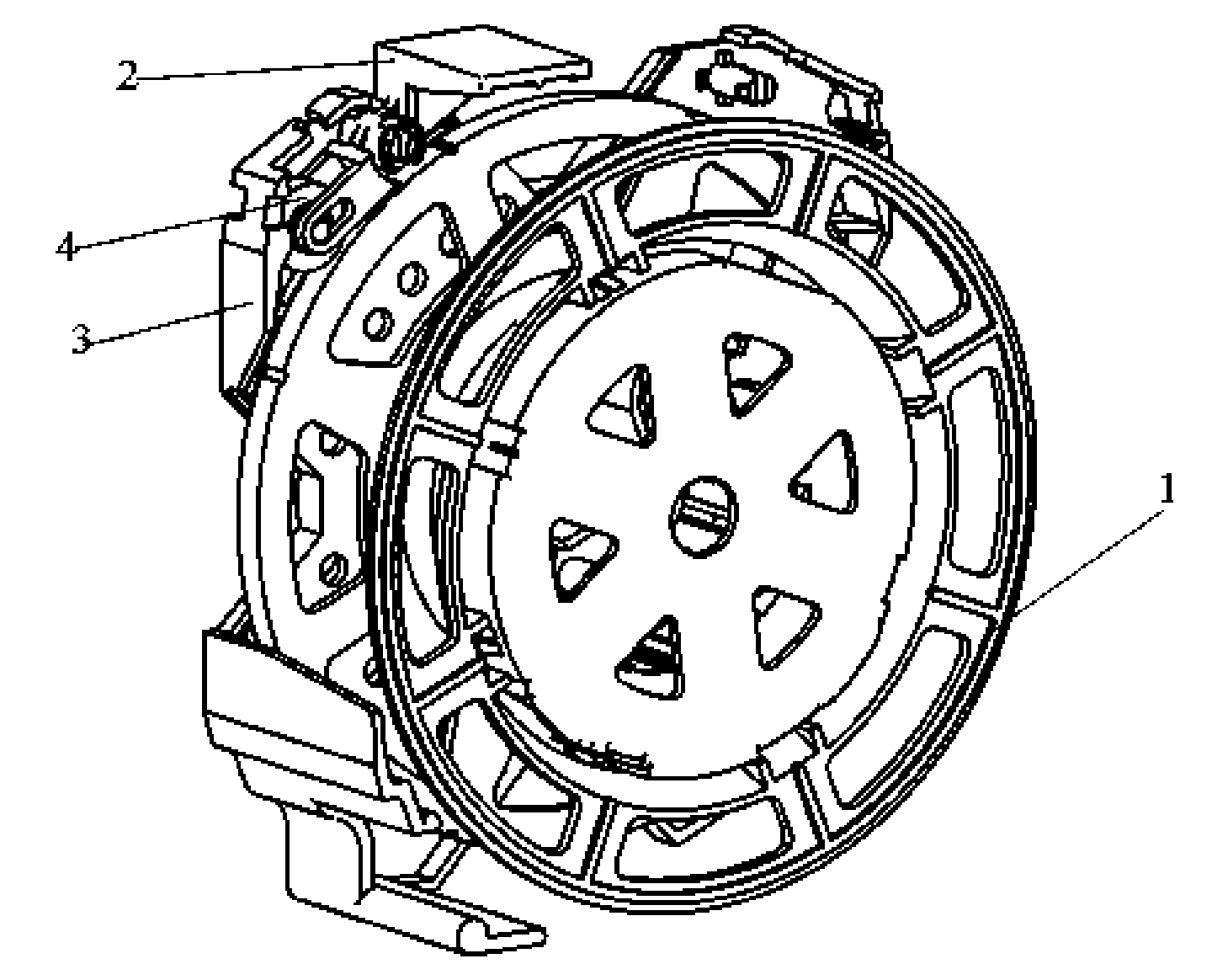
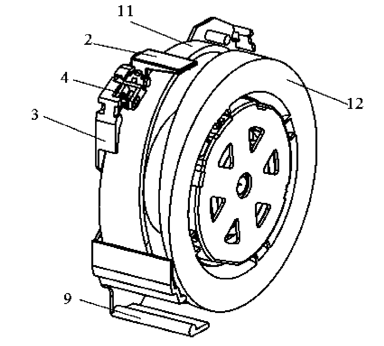
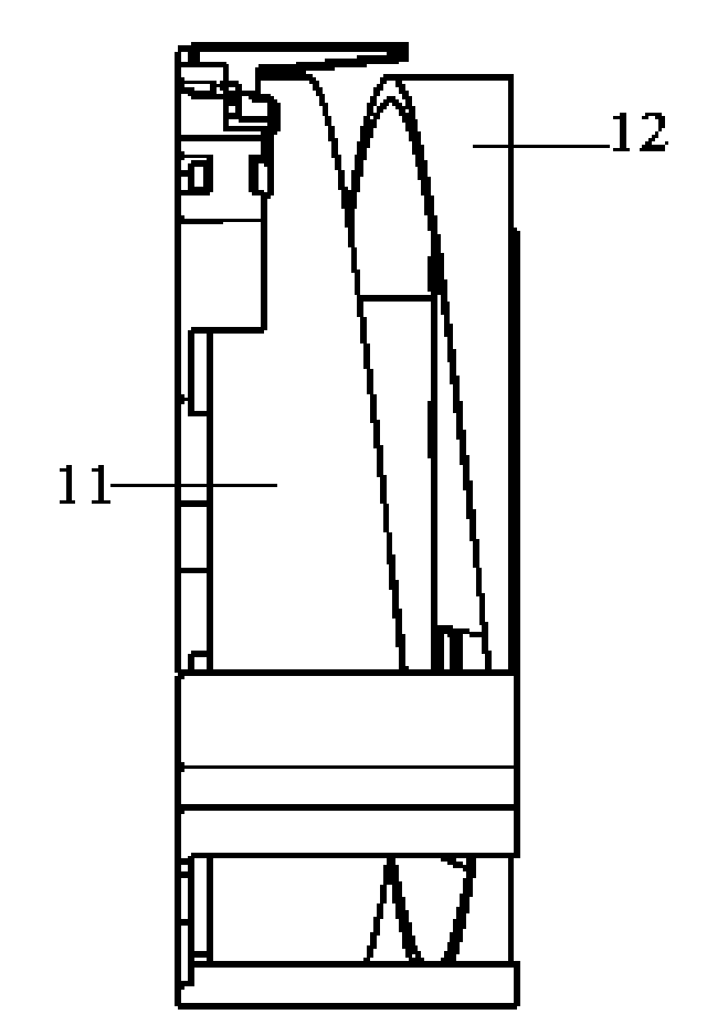
[0028] The cable reel with automatic wiring function of the present invention will be further described in detail in conjunction with the accompanying drawings and specific embodiments, wherein the same structure as the prior art will continue to use its labels and will not be described in detail again:

[0029] Such as Figure 2 to Figure 4 As shown, the wire reel of the present invention includes a left wheel disk and a right wheel disk forming a wire reel, and a bobbin (not shown) that connects the two in the middle and is provided with a concentric rotating shaft hole, so that it can be wound on The power cord (not shown) on the bobbin will not come out or mess up between the left wheel disc and the right wheel disc. The tops of the left and right roulettes protrude inwardly to form a left limit baffle 11 and a right limit baffle 12. Of course, the two limit baffles can also be fixedly arranged on the outer edges of the left and right roulettes. . The limit baffles on bo...


PUM


Abstract

The invention discloses an automatic wiring structure for a wire coiler, which comprises a wire coiling wheel, wherein a support is arranged on one side of the wire coiling wheel, and a spring coiling box is arranged on the other side of the wire coiling wheel; a return wire key and a braking wheel are arranged on the support side; a cylindrical limit baffle is convexly arranged on the periphery of a left wheel disc of the wire coiling wheel inwards, and a cylindrical limit baffle is convexly arranged on the periphery of a right wheel disc of the wire coiling wheel inwards; corresponding curve structures are formed on edges of the cylindrical limit baffles; and a gap is reserved between the two limit baffles. By the automatic wiring structure for the wire coiler, a power wire can wind on a wire coiling shaft uniformly, and is prevented from winding excessively at a certain position; and the power wire is pulled out layer by layer sequentially without generating the knot tying condition, so the satisfaction degree of users is improved.

Description

technical field [0001] The invention relates to a vacuum cleaner; in particular, it relates to a wire reel with automatic wiring function. Background technique [0002] Generally, a vacuum cleaner is a device that uses a vacuum to generate suction to inhale air, make the air flow through various filters, filter foreign objects in the air, and clean the room. [0003] Generally speaking, a vacuum cleaner mainly includes a suction device and a suction pipeline. The suction device mainly formed by a motor and a fan is arranged in the body. The suction pipeline includes a suction head and a suction pipe. The suction head has a downward opening. The suction port communicates with the air inlet of the fan inside the body through the telescopic pipe and the flexible pipe of the suction pipe. When the vacuum cleaner is running, the motor drives the impeller of the fan to rotate at a high speed, exhausting the air in the vacuum cleaner, forming an instantaneous vacuum in the vacuum ...

Claims


Application Information

Patent Timeline
Patent Type & Authority Applications(China)
IPC IPC(8): A47L9/26H02G11/02
Inventor 任光智孟庆琛
Owner LG ELECTRONICS (TIANJIN) APPLIANCES CO LTD
Learn More