Workpiece positioning and clamping device for thread cutting machine

A thread processing and clamping device technology, applied in positioning devices, metal processing machinery parts, metal processing equipment, etc., can solve problems such as errors, large deviations in processing or measurement results, etc., to overcome torsion and bending deformation, clamping Positioning is simple and fast

Active Publication Date: 2011-05-04
陕西汉江机床有限公司
View PDF0 Cites 34 Cited by
  • Summary
  • Abstract
  • Description
  • Claims
  • Application Information

AI Technical Summary

Problems solved by technology

However, the existing positioning and clamping devices assume that the axial center positions of the two ends of the workpiece are the axial center positions of each section of the entire workpiece. The measurement result must be that the closer to the middle position, the greater the deviation

Method used


Image

  • Workpiece positioning and clamping device for thread cutting machine
  • Workpiece positioning and clamping device for thread cutting machine
  • Workpiece positioning and clamping device for thread cutting machine

Examples


Embodiment Construction

[0015] The present invention will be further described below with reference to the drawings and embodiments.

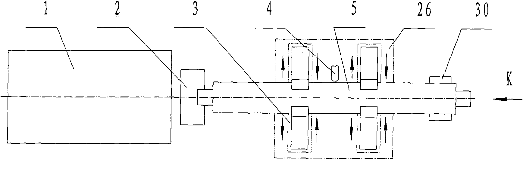
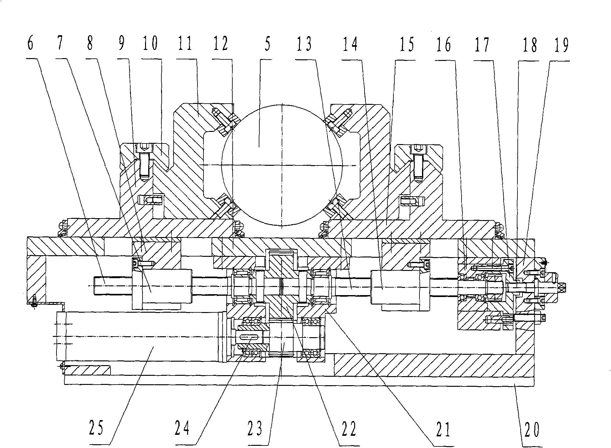
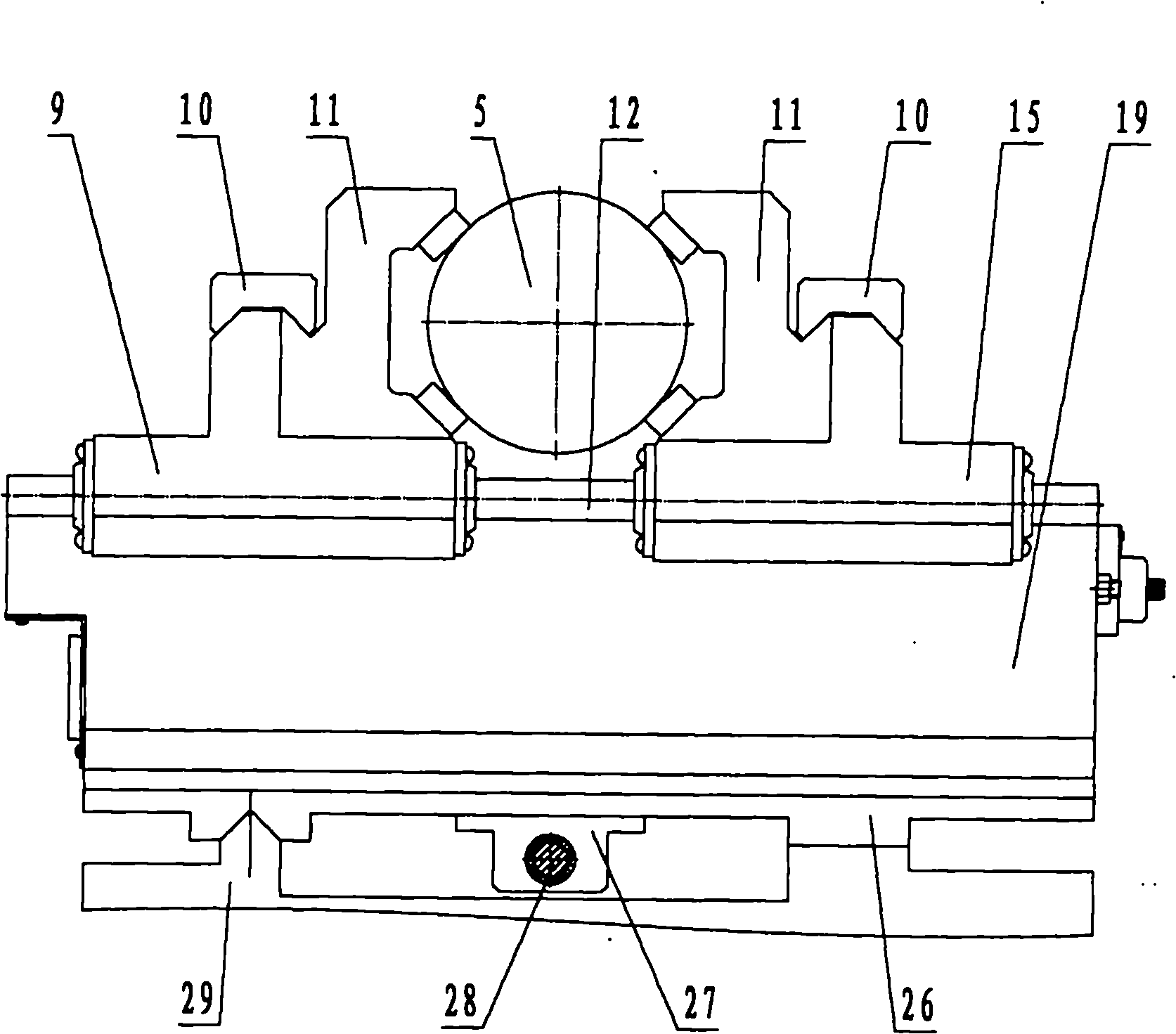
[0016] The thread processing machine tool workpiece positioning and clamping device of the present invention is composed of a support, a running mechanism fixedly installed on the upper part of the support, and a transmission mechanism installed in the inner cavity of the support. The transmission mechanism converts rotary motion into linear motion and drives the running mechanism to work. This device is used in pairs, and is fixed on the longitudinal carriage 26 of the machine tool together with the machine tool system. The tool system 4 is located at the center of the longitudinal carriage 26. A set of this device is installed on each side of the longitudinal carriage 26. The longitudinal carriage 26 is located On the guide rail of the machine bed 29, such as figure 1 image 3 Shown. During thread cutting, the machine tool headstock chuck 2 clamps one end of the work ...


PUM


Abstract

The invention discloses a workpiece positioning and clamping device for a thread cutting machine, comprising a supporting seat with an inner cavity, a running mechanism arranged on the upper plane of the supporting seat and a drive mechanism arranged inside the cavity of the supporting seat. The running mechanism consists of two V-shaped claws, a left dragging plate and a right dragging plate, wherein the openings of the two V-shaped claws opposite and the left dragging plate and the right dragging plate form a pair of jaws capable of opening and closing; the drive mechanism is arranged in the cavity of the supporting seat and comprises a pneumatic motor fixed at one side of the cavity of the supporting seat, a set of gears and pinions installed in the center of the cavity of the supporting seat in a meshed way, a left handed ballscrew pair and a right handed ballscrew pair, wherein the pinions are sleeved with the motor by a shaft, the two ballscrew pairs are inserted into inner bores of the gears by shafts, and ball nuts are respectively and fixedly connected with the left dragging plate and the right dragging plate. The device has functions of excircle automatic positioning andself-adaptively clamping and protecting and can stably follow up the cutting motion of a cutter so that a certain cutting depth is kept between the cutter and the excircle of each section of a workpiece.

Description

Technical field [0001] The invention relates to a workpiece positioning and clamping device of a machine tool, in particular to a workpiece rotation positioning and clamping device of a thread processing machine tool. technical background: [0002] The processing and measurement of cylindrical spiral parts (such as ball screws, trapezoidal screws, compressors and injection molding machine screws, and various cylindrical worms) of existing thread processing machine tools have always used a center hole positioning and clamping device, and the head on the device The tailstock center tightens the center holes at both ends of the workpiece and uses it as the center of rotation of the workpiece. The shift fork drives the workpiece to rotate for processing or measurement. In processing or measurement, especially when turning and milling slender threaded parts, the bending deformation of the slender part caused by the rotation and the milling force will cause machining or measurement dev...

Claims


Application Information

Patent Timeline
Patent Type & Authority Applications(China)
IPC IPC(8): B23Q3/06
Inventor 李军姚博世赵仲琪曹汉宝
Owner 陕西汉江机床有限公司
Why Eureka
Try Eureka