Suspension valve, oil gas suspension system and engineering vehicle

A technology of oil-pneumatic suspension and suspension, which is applied in the direction of suspension, elastic suspension, interconnection system, etc., can solve the problems of increasing hydraulic components, high hydraulic pressure and air pressure, and lifting suspension, so as to improve simplicity, Achieve long-term maintenance and avoid complicated effects of control

Active Publication Date: 2013-03-20
ZOOMLION HEAVY IND CO LTD
View PDF1 Cites 0 Cited by
  • Summary
  • Abstract
  • Description
  • Claims
  • Application Information

AI Technical Summary

Problems solved by technology

[0005] However, this existing oil-pneumatic suspension technology uses a two-position two-way valve to perform rigid-flexible conversion, which is affected by the suspension oil cylinder. In the rigid state, the suspension system cannot be effectively locked. The above-mentioned two-position two-way valve directly bears the vehicle pressure, because the two-position two-way valve bears relatively large hydraulic pressure and air pressure, when the air pressure changes, there is a possibility of automatically converting flexibility to rigidity
In addition, the suspension valve gives priority to raising the suspension, which makes the logic relationship of the suspension valve complex, and the number of hydraulic components must be increased to realize the lifting function, which also increases the difficulty of logic control

Method used


Image

  • Suspension valve, oil gas suspension system and engineering vehicle
  • Suspension valve, oil gas suspension system and engineering vehicle
  • Suspension valve, oil gas suspension system and engineering vehicle

Examples


Embodiment Construction

[0041] Specific embodiments of the present invention will be described in detail below in conjunction with the accompanying drawings. It should be understood that the specific embodiments described here are only used to illustrate and explain the present invention, and are not intended to limit the present invention.

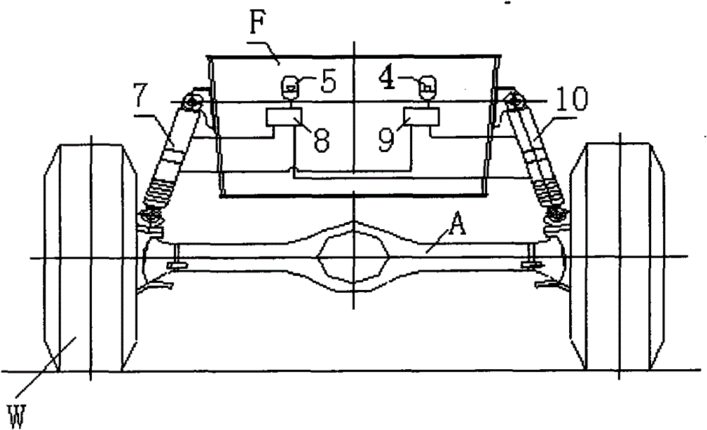
[0042] It should be noted that the orientation words used below for clarity and convenience, such as front left, front right, rear left, and rear right, are all the same as the actual installation of the oil-pneumatic suspension system on the engineering vehicle. It does not constitute a limitation to the protection scope of the present invention.

[0043] see figure 1 , figure 1 It shows the general installation form of the suspension valve in the oil-pneumatic suspension system, wherein the two sides of each axle A are symmetrically provided with suspension oil cylinders 7, 10, and the upper ends of the suspension oil cylinders 7, 10 are hinged on the frame ...


PUM


Abstract

Disclosed is a suspension valve, which comprises an oil inlet switch lock-up valve (22), an oil return switch lock-up valve (21) and differential pressure sensing and logic control units. The differential pressure sensing and logic control units include a logic shuttle valve (23), a differential pressure sensing and locking valve (24) and a guide control valve (25). The oil return switch lock-up valve (21) can open and lock the oil return path, and the oil inlet switch lock-up valve (22) can open and lock the oil inlet path. The logic shuttle valve (23) compares the pressure logics between a rod side chamber of a suspension oil cylinder and a rodless chamber of the suspension oil cylinder. The differential pressure sensing and locking valve (24) senses the differential pressure between the rod side chamber of the suspension oil cylinder and the rodless chamber of the suspension oil cylinder, as well as connects and locks the two chambers. Besides, an oil-gas suspension system and an engineering vehicle adopting said suspension valve are also disclosed. By employing the differential pressure sensing and logic control units, the invention more reliably enables long-time maintaining of both a rigid mode and a flexible mode of the suspension system, realizes a quick and reliable conversion between the rigid mode and the flexible mode, effectively reduces the number of units in the suspension valve of the axle suspension system, thus achieving an easy and convenient control.

Description

technical field [0001] The invention relates to a suspension valve. In addition, the present invention also relates to an oil-pneumatic suspension system and an engineering vehicle including the suspension valve. Background technique [0002] Hydro-pneumatic suspension systems are widely used in various mobile construction machinery, such as wheeled loading and unloading trucks, mine dump trucks, wheeled excavators and mobile cranes. [0003] The existing oil-pneumatic suspension system is mainly realized by the combination of suspension cylinder and accumulator, the combination of suspension cylinder and accumulator plus suspension valve, and various manufacturers basically adopt the combination of suspension cylinder and accumulator plus suspension valve. . see figure 1 , wherein the two sides of each axle A are symmetrically provided with suspension oil cylinders 7, 10, the upper ends of the suspension oil cylinders 7, 10 are hinged on the frame F or the vehicle body, ...

Claims


Application Information

Patent Timeline
Patent Type & Authority Patents(China)
IPC IPC(8): B60G21/073B60G13/08
CPCB60G17/052B60G17/056
Inventor 詹纯新刘权李英智张建军郭堃李义郭纪梅胡廷江王启涛刘学检冯科喜奉松生
Owner ZOOMLION HEAVY IND CO LTD
Why Eureka
Try Eureka