
Hydraulic control circuit and hydraulic motor control system

A control circuit, hydraulic motor technology, applied in servo motors, servo motor components, servo meter circuits, etc., can solve the problems of hydraulic motor reversal, leakage, and hydraulic motor can not work stably

Active Publication Date: 2011-05-04
ZOOMLION HEAVY IND CO LTD
View PDF6 Cites 5 Cited by
  • Summary
  • Abstract
  • Description
  • Claims
  • Application Information

AI Technical Summary

Problems solved by technology

For example, for a hydraulic motor, when its oil supply flow value is lower than its minimum stable flow value, due to the phenomenon of oil leakage inside the hydraulic motor, the hydraulic motor will not work stably, especially when the hydraulic motor works at In the heavy load state, the hydraulic motor may also reverse and shake, which seriously threatens the safety of people and equipment
[0003] In the prior art, there is no simple and feasible method to solve this technical problem

Method used


Image

  • Hydraulic control circuit and hydraulic motor control system
  • Hydraulic control circuit and hydraulic motor control system
  • Hydraulic control circuit and hydraulic motor control system

Examples


Embodiment Construction

[0049] Specific embodiments of the present invention will be described in detail below in conjunction with the accompanying drawings. It should be understood that the specific embodiments described here are only used to illustrate and explain the present invention, and are not intended to limit the present invention.

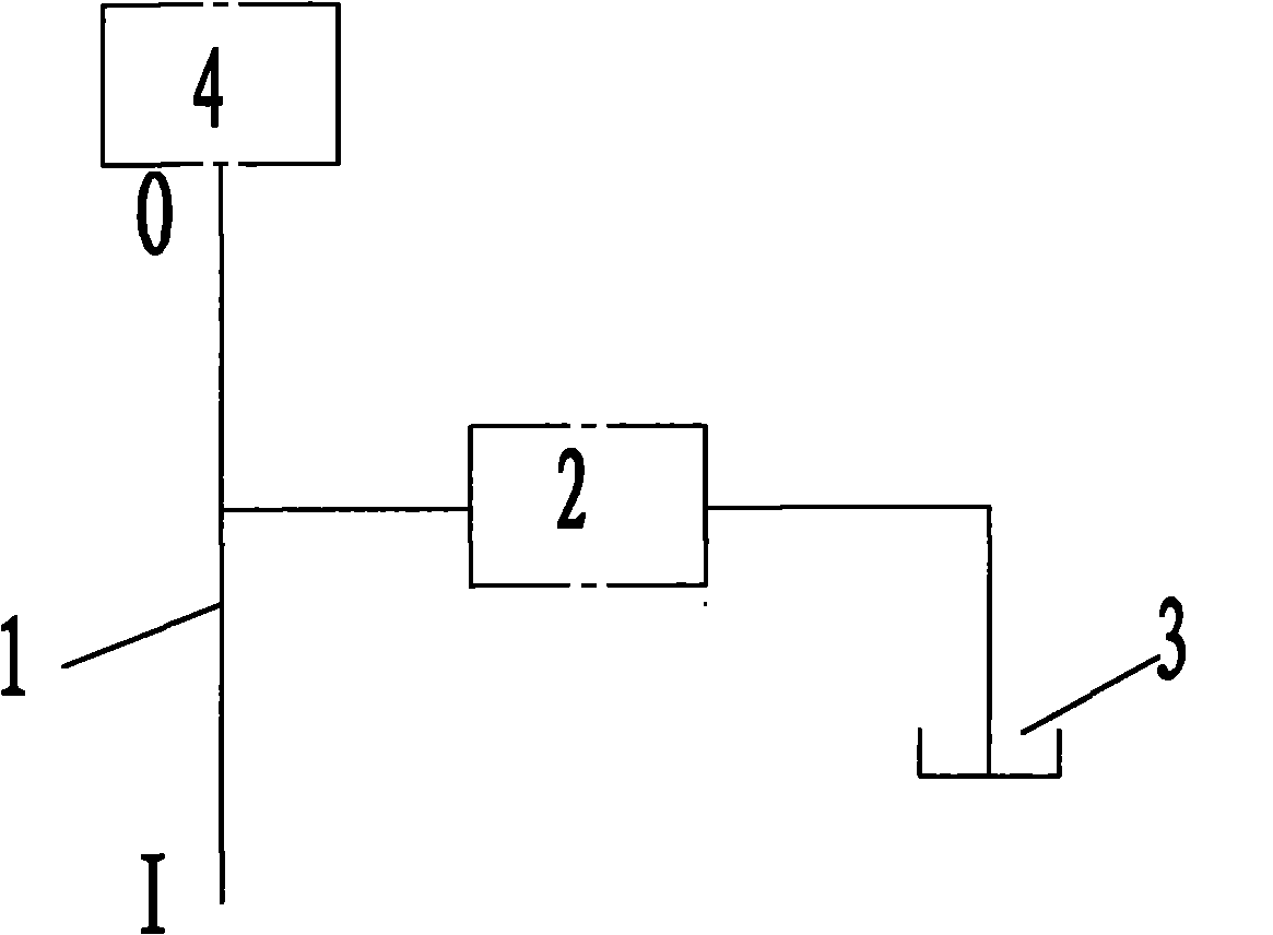
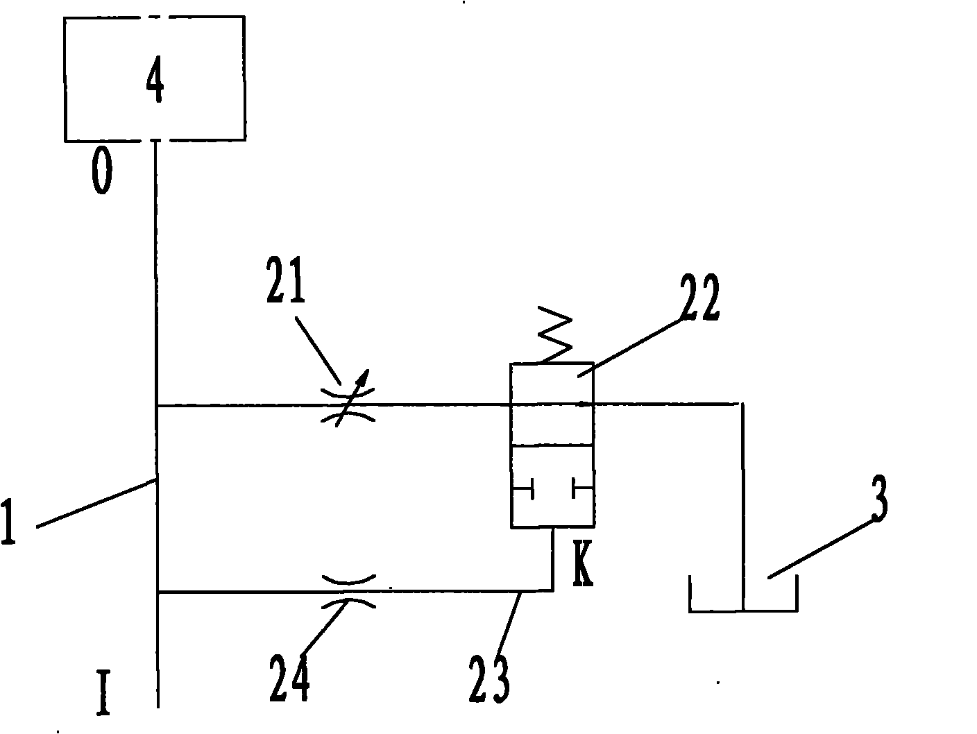
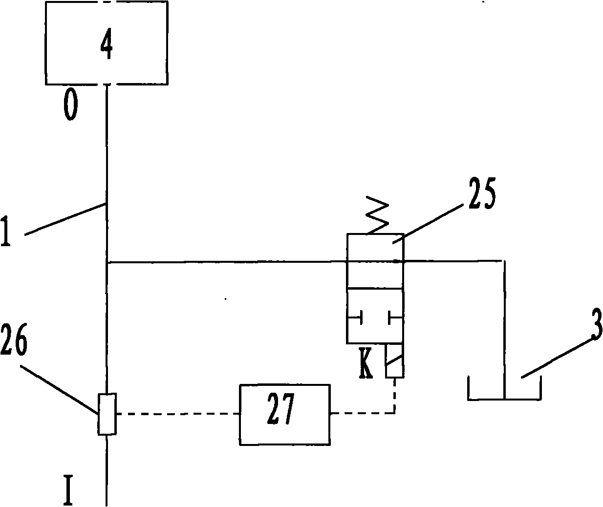
[0050] like figure 1 As shown, the present invention firstly provides a hydraulic control circuit, which mainly includes a main oil circuit 1, an automatic reversing unit 2 and a fuel tank 3, the main oil circuit 1 has an oil inlet I and an oil outlet O, and the The automatic reversing unit 2 is connected in series with the oil tank 3 and bypassed on the main oil circuit 1 . When the flow value of the oil inlet I of the main oil circuit 1 is less than a predetermined value, the automatic reversing unit 2 is turned on, so that the oil in the main oil circuit 1 flows back to the oil tank 3 through the automatic reversing unit 2 ; When the flow value of the oil inl...


PUM


Abstract

The invention provides a hydraulic control circuit. The hydraulic control circuit comprises a main oil circuit (1), an automatic reversing unit (2) and an oil tank (3), wherein the main oil circuit (1) is provided with an oil inlet (I) and an oil outlet (O); the automatic reversing unit (2) is connected in series with the oil tank (3) and is in side joint with the main oil circuit (1); when the flow value of the oil inlet (I) of the main oil circuit (1) is smaller than a predetermined value, the automatic reversing unit (2) is switched on to ensure that inlet oil of the main oil circuit (1) passes through the automatic reversing unit (2) and flows back to the oil tank (3); and when the flow value of the oil inlet (I) of the main oil circuit (1) reaches the predetermined value, the automatic reversing unit (2) is switched off to ensure that the inlet oil of the main oil circuit (1) flows to the oil outlet (O). The invention also provides a hydraulic motor control system, which controlsa hydraulic motor mainly through the hydraulic oil control circuit. The technical scheme can ensure that the main oil circuit provides a required initial flow value outwards through the oil outlet thereof.

Description

technical field [0001] The invention relates to a hydraulic control circuit and a hydraulic motor control system. Background technique [0002] In the hydraulic control system, some actuators have certain requirements on the flow value of the oil supply. For example, for a hydraulic motor, when its oil supply flow value is lower than its minimum stable flow value, due to the phenomenon of oil leakage inside the hydraulic motor, the hydraulic motor will not work stably, especially when the hydraulic motor works at In the heavy load state, the hydraulic motor may also reverse and shake, which seriously threatens the safety of people and equipment. [0003] In the prior art, there is no simple and feasible method to solve this technical problem. Contents of the invention [0004] An object of the present invention is to provide a hydraulic control circuit, which can provide the required initial flow value for the actuator or other occasions with specific requirements on the...

Claims


Application Information

Patent Timeline
IPC IPC(8): F15B11/02F15B13/02
CPCF15B11/0423F15B2211/50536F15B2211/7058
Inventor 郭海保张劲谢海波李美香左春庚魏星简桃凤
Owner ZOOMLION HEAVY IND CO LTD
Learn More