Surface texture measuring machine and a surface texture measuring method

一种表面性质、测定物的技术,应用在测量装置、机械测量装置、采用机械装置等方向,能够解决耗费时间、测定物划伤等问题

Active Publication Date: 2011-05-04
MITUTOYO CORP
View PDF8 Cites 20 Cited by
  • Summary
  • Abstract
  • Description
  • Claims
  • Application Information

AI Technical Summary

Problems solved by technology

[0012] In the surface property and shape measuring machine of Document 2, since the preliminary measurement is composed of multiple steps, and the preliminary measurement is performed on the surface of the object to be measured using the probe, there is a problem that the preliminary measurement takes a lot of time.
In addition, there is a problem that the object to be measured may be scratched by the probe.

Method used


Image

  • Surface texture measuring machine and a surface texture measuring method
  • Surface texture measuring machine and a surface texture measuring method
  • Surface texture measuring machine and a surface texture measuring method

Examples


no. 1 example

[0088] Figure 1 to Figure 5 )>

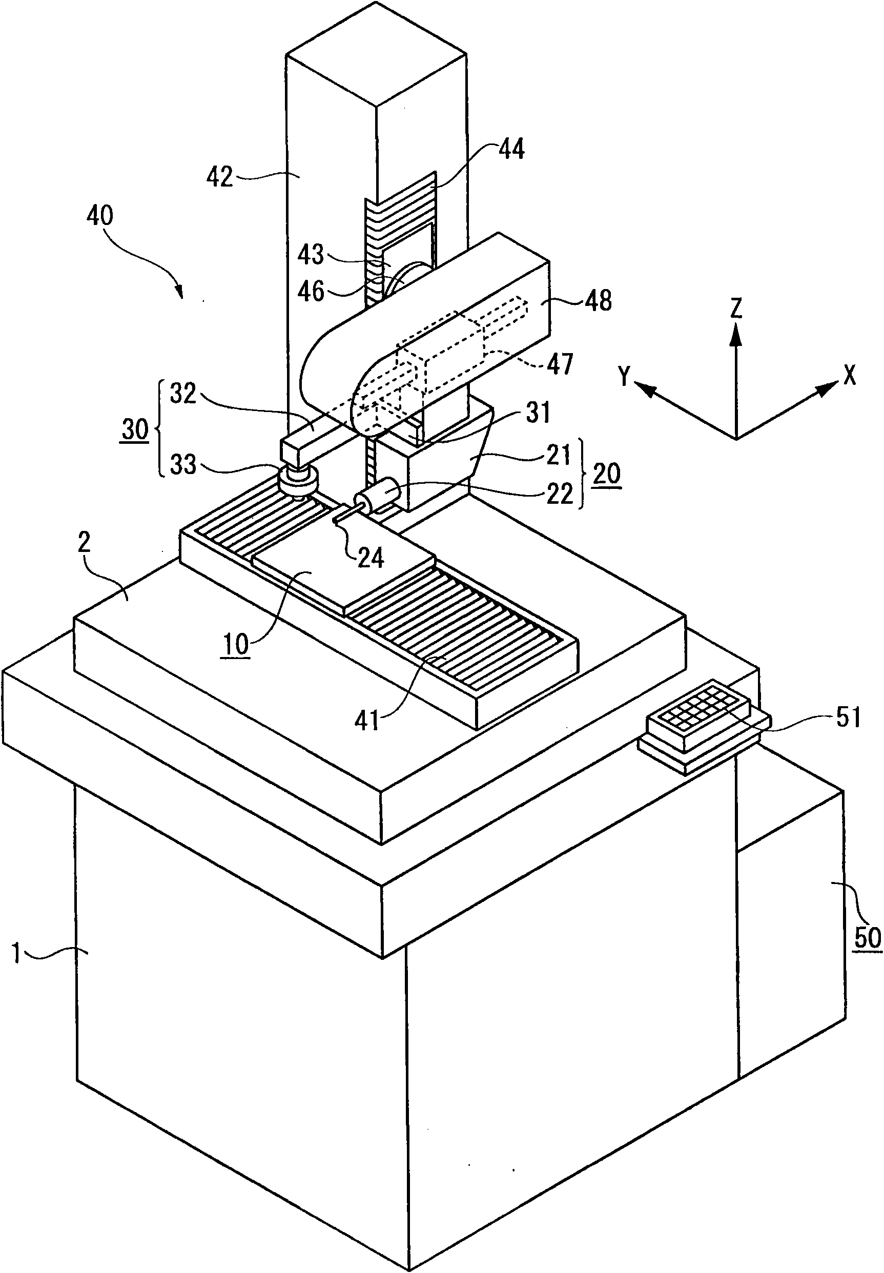
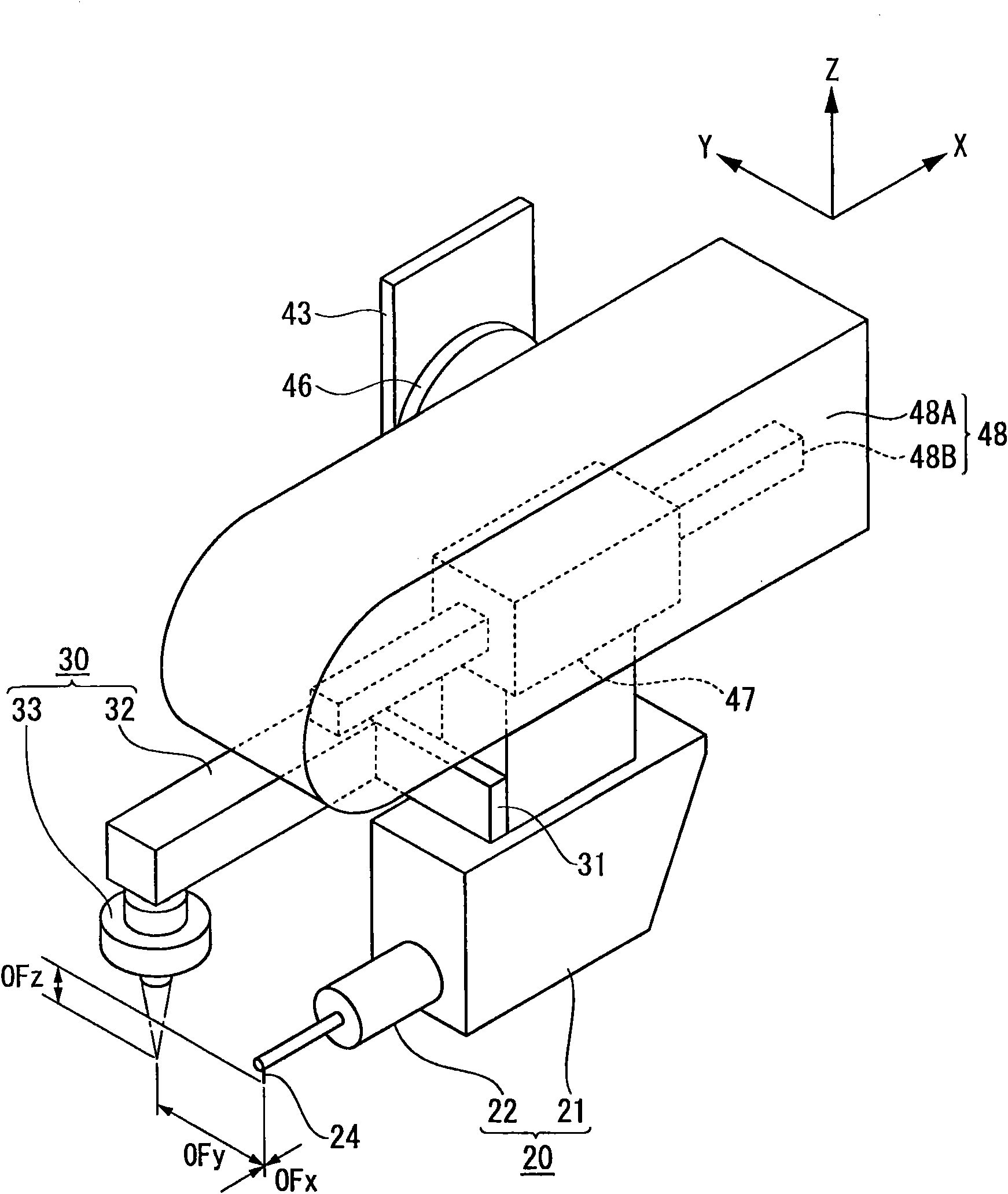
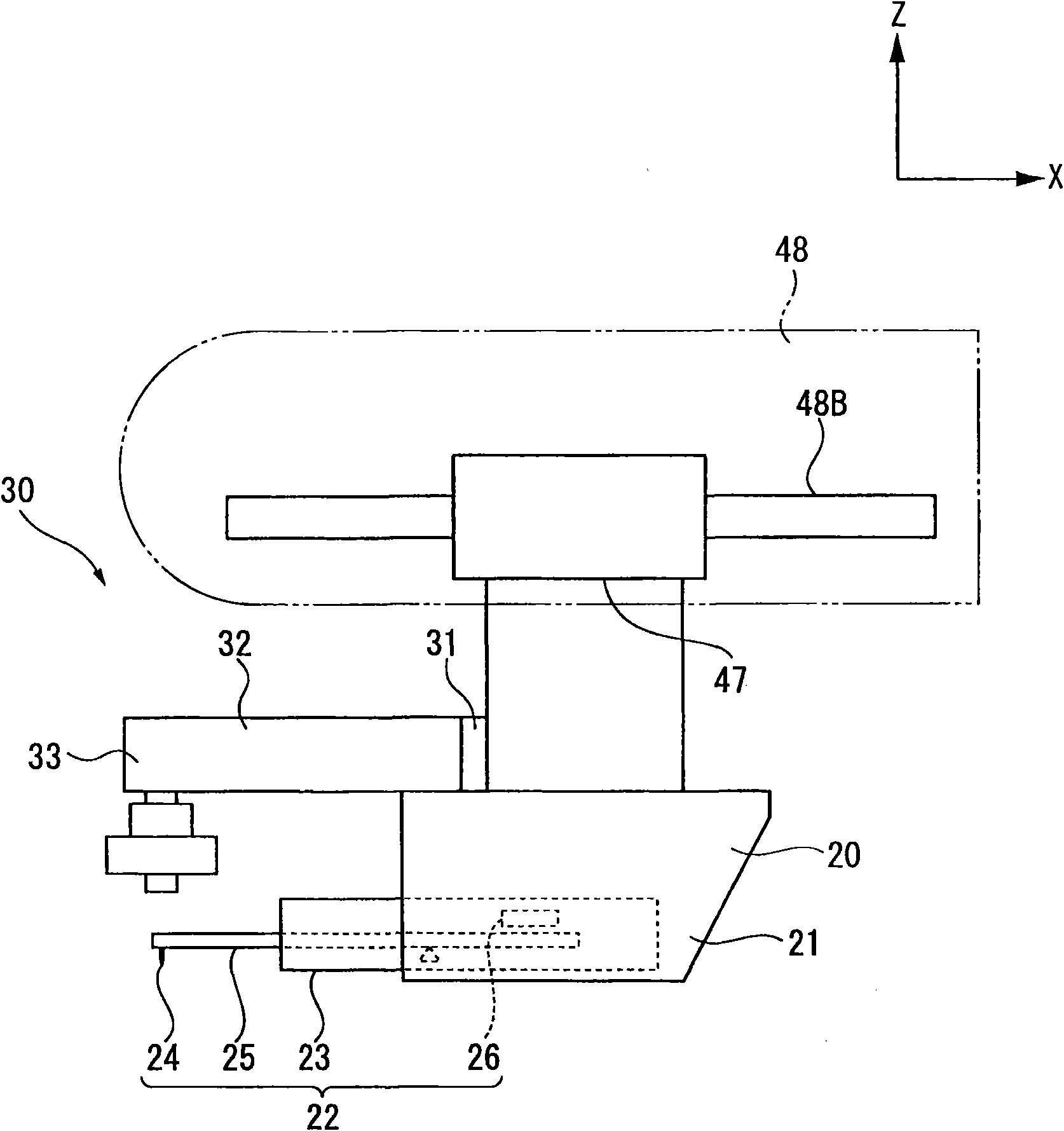
[0089] Such as figure 1 and figure 2 As shown, the surface property and shape measuring machine of this embodiment has: a setting table 1, a base 2 fixed on the setting table 1, a workbench 10 carried on the base 2 and an object to be measured thereon, A contact detector 20 with a probe 24 that is in contact with the surface of the object to be measured, an image detector 30 that captures an image of the surface of the object to be measured, and a relative movement of the contact detector 20 and the image detector 30 to the table 10 The relative movement mechanism 40, the control device 50.

[0090] The relative moving mechanism 40 includes: a Y-axis drive mechanism 41 as a first moving mechanism that is installed between the base 2 and the table 10 to move the table 10 in one direction (Y-axis direction) in the horizontal direction; The column 42 on the upper surface of the base 2, the Z slide block 43 as an elevating member which is arr...

no. 2 example

[0141] In the description of the second embodiment, the same reference numerals are assigned to the same constituent elements as those of the first embodiment, and description thereof will be omitted.

[0142] The surface property and shape measuring machine of the second embodiment can adjust the posture of the object to be measured to a posture parallel or perpendicular to the specified measurement axis, such as Figure 20 and Figure 21 As shown, a rotary table 10A is added to the surface property and shape measuring machine of the first embodiment.

[0143] The turntable 10A is installed on the table 10 and rotates according to the command of the control device 50 . Thereby, the object W to be measured is rotated in the horizontal plane (in the XY plane). In this example, the object W to be measured is cylindrical.

[0144] The image probe 30 has an appropriate structure for positioning the object W to be measured at the focal position of the objective lens 35 in additi...

no. 3 example

[0175] In the description of the third embodiment, the same reference numerals are assigned to the same constituent elements as those of the first embodiment, and description thereof will be omitted.

[0176] The surface property and shape measuring machine of the third embodiment can automatically set the probe of the contact detector to the measurement start position of the object based on the image of the object captured by the image sensor. Such as Figure 32 and Figure 33 As shown, the structures of the image probe 30 and the control device 50 are different from the surface property and shape measuring machine of the first embodiment.

[0177] The image probe 30 of the present embodiment includes: a cylindrical probe body 32 integrally connected to the X slider 47 together with the contact detector 20 via a connecting member 31; 24 An axis perpendicular to the direction in which the contact detector 20 and the table 10 move relative to each other (X-axis direction) and...


PUM


Abstract

A surface texture measuring machine includes: a stage, a contact-type detector (20) having a stylus, an image probe (30), a relative movement mechanism (40) and a controller (50). The controller (50) includes: a center position calculating unit that, when the image probe enters position data of at least three points on a circular contour of a circular concave portion or a circular convex portion of an object, approximates the entered position data to a circle to obtain a center position of the circle; and a stylus setting unit that, after calculating the center position, operates the relative movement mechanism to position the stylus of the contact-type detector at the center position.

Description

technical field [0001] The present invention relates to a surface property and shape measuring machine and a surface property and shape measuring method for measuring the surface shape and surface roughness of an object to be measured. Specifically, it relates to a surface property and shape measuring machine and a surface property and shape measuring method provided with a contact detector having a probe and an image sensor. Background technique [0002] There is known a surface property and shape measuring machine as follows, in which the probe is moved along the surface of the object to be measured while the probe is in contact with the surface of the object to be measured, and at this time, the surface shape of the object to be measured is detected. The displacement of the measuring head caused by surface roughness and surface roughness is used to measure the surface properties and shape of the object to be measured based on the displacement of the measuring head, such a...

Claims


Application Information

Patent Timeline
Patent Type & Authority Applications(China)
IPC IPC(8): G01B11/24G01B11/30H04N5/232
CPCG01B5/008G01B11/005G01B11/245G01B21/047
Inventor 松宫贞行大森义幸有田贞治平野宏太郎福本泰小松浩一竹村文宏
Owner MITUTOYO CORP
Why Eureka
Try Eureka